Operating Instructions
– LBA63 TOLL HIGHWAYS – 2019 Version
65
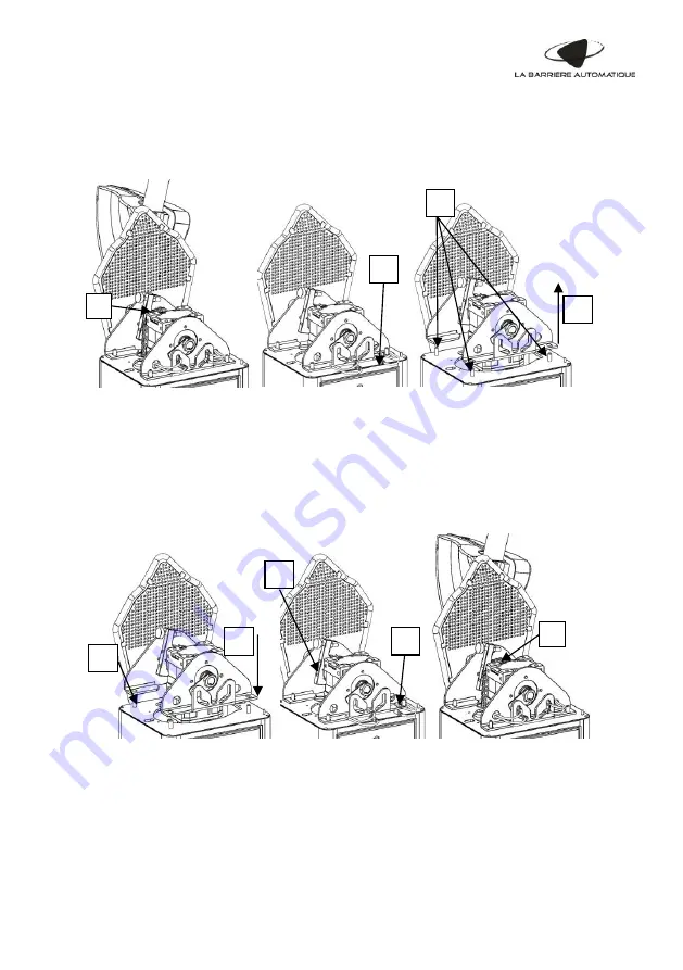
18.3 Replacing the reduction gear assembly
The reduction gear assembly on the LBA 63 TOLL HIGHWAYS is replaced using the following
procedure:
A-
Remove the cover, the unhinging plate and screw the opening stop to be able to open the
barrier further than the vertical stop (to release all the compensation)
B-
Once the barrier is open further than the vertical, remove the chain-spring compensation
system by removing the quick-release fastener of the chain on the cog wheel
C- Loosen the inductive sensors and remove them through the holes on either side of the
stirrup
D- Disconnect the reduction gear connected on the frequency converter
E-
Loosen and remove the four lock nuts from the reduction gear stirrup brackets
F-
Remove the reduction gear assembly
G- Insert the new reduction gear assembly in place of the old one
H- Tighten the two lock nuts located on the side of the boom, aligning the flange with the
housing edge
I-
Tighten the two screw nuts that fix the bearing to the stirrup
J-
Tighten the other two lock nuts on the side of the sensors
K-
Connect the new reduction gear unit to the converter at terminals U, V, W and to the earth
L-
Replace the inductive sensors as they were before the replacement
M- Put the compensation system back on the cog wheel
N-
Review the adjustment of the end stops and position sensors (see paragraph “9.3 Adjusting
end stops and sensors”)
B
C
E
F
I
G
L
M
H


