


C
REATING
C
USTOM
C
OMPONENTS
IN
L
ATTICE
M
ICO
S
YSTEM
:
Specifying User-Configurable Parameters
LatticeMico32 Hardware Developer User Guide
79
Adding Non-RTL Parameters
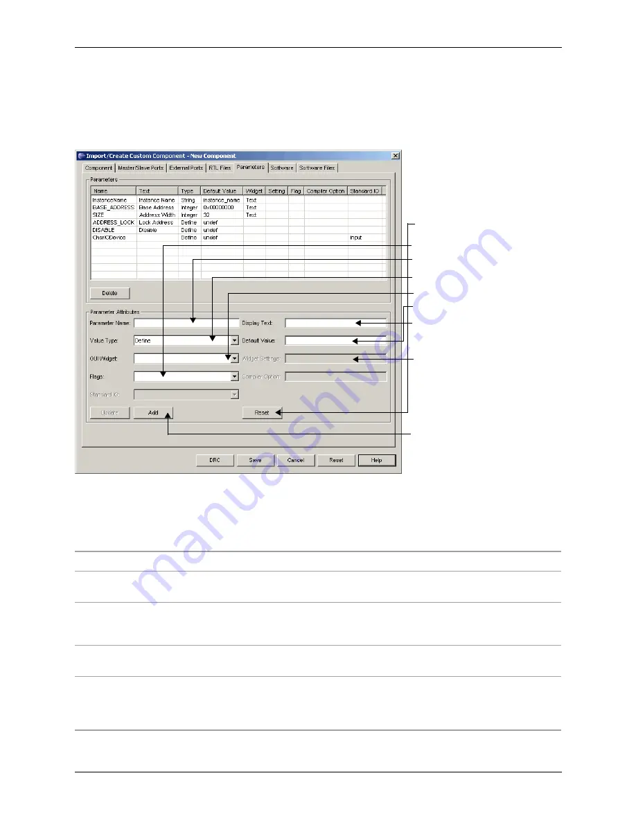
Figure 41 shows the steps required for adding non-RTL parameters.
Table 10 lists the options available in the Parameters tab of the Import/Create
Custom Component dialog box
Figure 41: Steps Involved in Adding Non-RTL Parameters
Step 1: Press Reset to reset all
fields.
Step 2: Deselect Flags.
Step 3: Enter parameter name.
Step 4: Select parameter’s value
type.
Step 5: Select GUI widget type.
Step 6: Provide default value.
Step 7: Enter text to be displayed
in component configuration dialog
box in MSB.
Step 8: Provide widget settings,
if widget is spinner or combo.
Step 9: Click
Add
button.
Table 10: Parameters Tab Options
Option
Description
Parameter Name
Specifies the name of the parameter to be passed to the Verilog source code.
When using Define types, be sure to make the name globally unique.
Display Text
Specifies the display text that will be placed adjacent to the specific control. Each
component, when added to the platform, brings up an individualized dialog box.
Each element in the dialog box has descriptive text placed adjacent to a control.
Value Type
Specifies the value type. Choose Define, String, Integer, List, or Frequency from
the drop-down menu.
Default Value
Specifies how each parameter or `define is initialized when a component is
added to the platform. This field is free-form, so you must be careful when
entering default values. Any type mismatch or incorrect data entered here will
impact the synthesis process later.


