


18
HDR-60 Base Board – Revision B
2.
Connect the USB-A to USB-A cable from your PC’s USB connector to the upper USB port on J12 on the HDR-
60 Base Board.
3.
Connect the 12 V wall power adaptor cable to J10 and check to see that the wall power adapter is plugged in to
a 120 VAC source.
4.
Start the ispVM System software. Select the menu items
Options > Autoscan Options > Custom Scan
.
5.
Select
Options > Cable
and
I/O Port Setup
. For the Cable Type, select
USB2
, then click
OK
.
6.
Push the
Scan
button. You should now see the LFE3-95/70 device listed in the New Scan Configuration Setup
window. In the device list, left-click on the
LatticeECP3
device to select it. If offered other selections, select
LFE3-70EA
.
7.
Click
Edit > Edit Device
to edit the device. A Device Information window will be opened. Click the
Select
but-
ton and select the package type
484-ball fpBGA
, then click
OK
.
8.
Click the
Device Access Options
drop-down menu control and select
SPI Flash Background Programming
.
A SPI Serial Flash Device window will open.
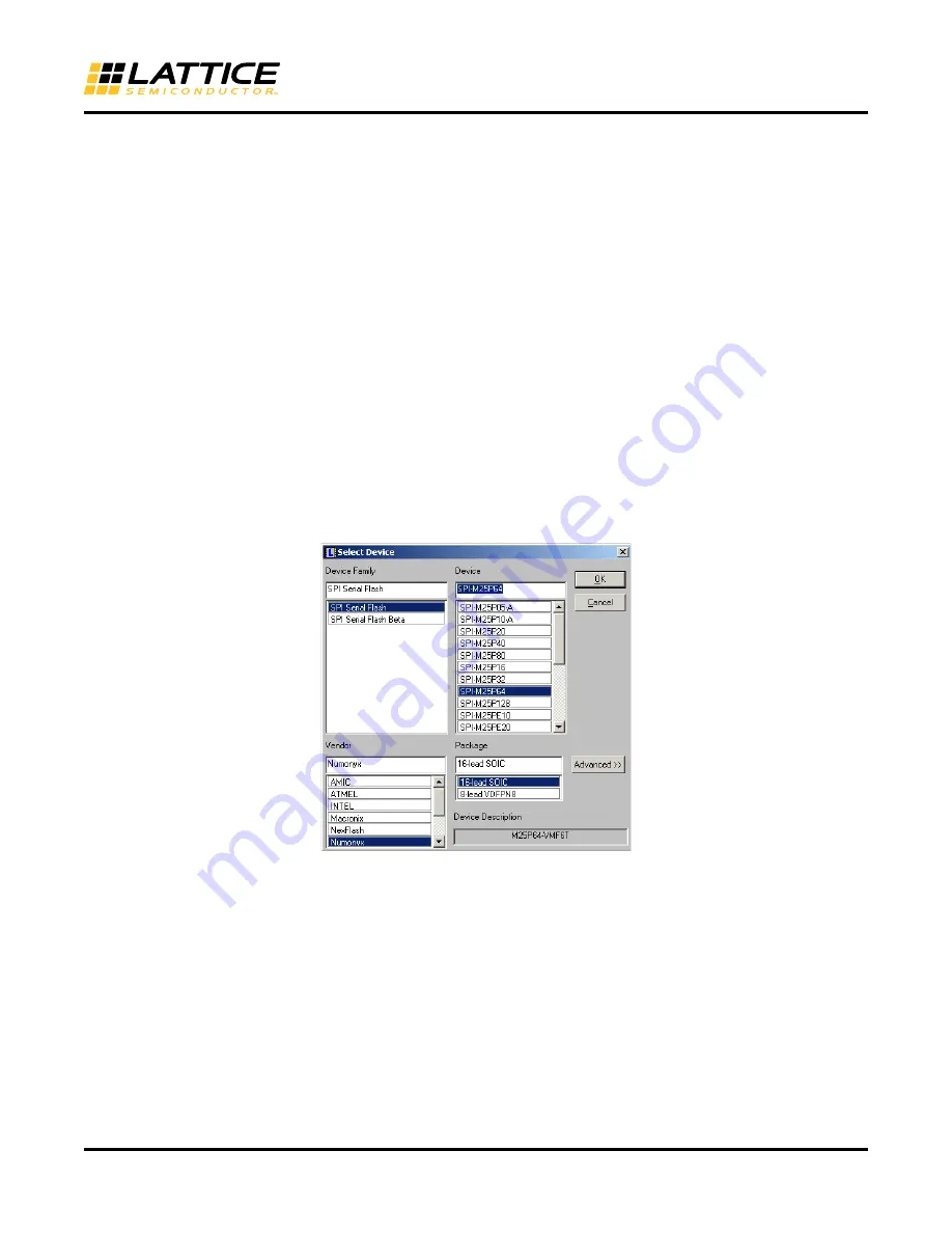
9.
Push the
Select
button and select the Vendor as
Numonyx
, the device as
SPI-M25P64
and the package
16-
lead SOIC
as shown in Figure 10. Push the
OK
button.
Figure 10. SPI Flash Device Selection
10. Click the data file
Browse
button and select the path to the LatticeECP3 “.BIT” bitstream file. Push the
Load
From File
button and then click
OK
to complete the SPI Flash device selection as shown in Figure 11. Again
click
OK
to exit the Device Information menu. The bitstream is now set up for downloading into the SPI Flash
as shown in Figure 12.


