


BL55-RU
(E)
5-1
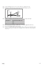
Fig. 5-1
A
C D E
J
F
G H
M
L
K
B
5. Input/Output Connectors
5-1. Connectors
Interface unit side
: R04-R12M (manufactured by TAJIMI ELECTRONICS CO., LTD.)
Cable side : R04-P12F (manufactured by TAJIMI ELECTRONICS CO., LTD.) ....... Waterproof type
: R03-PB12F (manufactured by TAJIMI ELECTRONICS CO., LTD.) ..... Non-waterproof type
Pin arrangement
Input/output specifications
A/B signal output
Analog output
A
A
+
COS
B
∗
A
−
COS
C
B
+
SIN
D
∗
B
−
SIN
E
Z
+
REF
F
∗
Z
−
REF
G
+
5 V (power supply)
H
0 V (power supply)
J
0 V (signal)
K
0 V (signal)
L
+
5 V S
M
0 V S
Table 5-1
•
0 V is the circuit ground, and it is not connected to the frame ground.
•
Make sure that the power supply voltage is 5 V DC
±
5 % at the input connector to the interface unit.
•
+5 V S and 0 V S are for checking the voltage (remote sensing function) applied to the input connector of
the interface unit. These voltages can be used to check and control for drops in the supply voltage due to
the cables. When using a power supply that cannot control power supply fluctuations, a power supply
input terminal can be used to reduce the supply voltage drops occurring due to the cable length. In this
case, connect the cable to the resp5 V or 0 V power supply.
•
The appropriate cable thickness is AWG28 to AWG24.
•
Connect all of the 0 V terminals to prevent mis-wiring.
•
Use shielded cables for all cabling.
•
Use twisted-pair cables for the output signals.
Use cables so that the following signals are paired: A and
∗
A, B and
∗
B, Z and
∗
Z, +SIN and
−
SIN,
+COS and
−
COS, +REF and
−
REF.
Summary of Contents for BL55-RU
Page 2: ...BL55 RU ...
Page 14: ...1 4 E BL55 RU ...
Page 30: ...3 14 E BL55 RU ...
Page 40: ...4 10 E BL55 RU ...
Page 48: ...7 2 E BL55 RU ...
Page 50: ...8 2 E BL55 RU ...
Page 62: ...1 4 G BL55 RU ...
Page 78: ...3 14 G BL55 RU ...
Page 88: ...4 10 G BL55 RU ...
Page 96: ...7 2 G BL55 RU ...
Page 98: ...8 2 G BL55 RU ...


