3-12
(E)
BL55-RU
Outside of suitable tube
Union
3-4-9. Removing the Scale
Use the following procedure to remove a scale that has been installed on a machine.
1
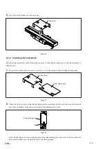
Use the slider holder to secure the slider to the scale unit.
Be sure to always use the slider holder.
2
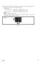
Remove the slider attachment screws.
3
Remove the scale unit attachment screws.
3-5. Air Injection Procedure
Chips, cutting oil, and other substances generated by cutting can frequently be scattered in the area around
the scale unit, especially when it is installed on a machine tool. Even when not using a machine tool, air
should be injected to the scale when installed on machines generating dust or when dust is prevalent in the
operating environment.
3-5-1. Installation
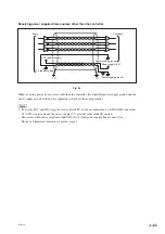
There are a total of three air inlets, one each on both sides of the scale unit and on the slider.
Supply air to all of the air inlets.
1
Remove the hex. socket head cap screws in the air inlets.
2
Wrap the sealing tape (obtained by customer) around the screw section of the supplied hex. socket-head
half-unions, and then screw into the air inlets.
Tightening torque: 1.5 N
·
m
3
Press a tube (available commercially, external diameter: 4 mm) into the hex. socket-head half-union.
Fig. 3-17
Summary of Contents for BL55-RU
Page 2: ...BL55 RU ...
Page 14: ...1 4 E BL55 RU ...
Page 30: ...3 14 E BL55 RU ...
Page 40: ...4 10 E BL55 RU ...
Page 48: ...7 2 E BL55 RU ...
Page 50: ...8 2 E BL55 RU ...
Page 62: ...1 4 G BL55 RU ...
Page 78: ...3 14 G BL55 RU ...
Page 88: ...4 10 G BL55 RU ...
Page 96: ...7 2 G BL55 RU ...
Page 98: ...8 2 G BL55 RU ...


