


BL55-RU
(E)
3-11
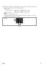
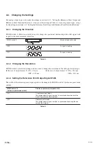
3-4-7. Checking the Operating Range
After mounting the scale unit and slider, be sure to always move the machine over its entire length to check
that the machine movement range is within the scale measuring length. During this check, make sure that
LED on the interface unit does not indicate an alarm. (A/B phase output types only) Refer to section 4-2 for
removing and attaching the cover of the interface unit.
Be careful that the scale movement range does not exceed the scale measuring length
+
range of movement.
If it does, the scale can be damaged.
Fig. 3-15
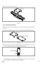
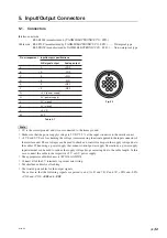
3-4-8. Securing the Head Cable
Secure the head cable with a cable clamp so that it does not get in the way of movement or operation.
The cable clamps are secured using a M4
×
10 hex. socket-head cap screw.
Note that the wiring should be made to allow enough room for machine movement during operation.
Fig. 3-16
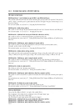
Speed alarm
Level alarm
Cable clamp (supplied)
Secure with M4
×
10 hex. socket-head cap screw
Summary of Contents for BL55-RU
Page 2: ...BL55 RU ...
Page 14: ...1 4 E BL55 RU ...
Page 30: ...3 14 E BL55 RU ...
Page 40: ...4 10 E BL55 RU ...
Page 48: ...7 2 E BL55 RU ...
Page 50: ...8 2 E BL55 RU ...
Page 62: ...1 4 G BL55 RU ...
Page 78: ...3 14 G BL55 RU ...
Page 88: ...4 10 G BL55 RU ...
Page 96: ...7 2 G BL55 RU ...
Page 98: ...8 2 G BL55 RU ...


