background image

IND-MD-TM-CS-TH-KT 

Larson Electronics, LLC


 Phone: (800) 369-6671 

 Fax: (903) 498-3364 

 www.larsonelectronics.com 

17 of 21

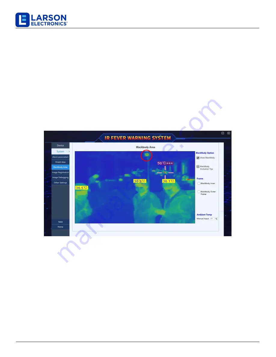
2.2.1  Black body area setting

The black body temperature measurement uses the actual temperature of the black body as the reference temperature. 

In order to make the device accurate temperature measurement, the black body target area must be framed. The specific 

equipment steps are as follows: 

1.

Click the "Settings" button in the main interface-> "System Settings"-> "Blackbody  Area"  to  enter  the  blackbody

area  setting  interface,  as shown in Figure 4-8

2.

Select  the  "Black  Frame"  option,  move  the  mouse  cursor  to  the infrared  image,  find  the  black  body

heating  target  surface  in  the infrared image, hold down the left mouse button and drag the frame to select the

center heating area of the black body target surface, and then click the lower left corner of the window Save

button

3.

Select the "Black frame" option again, move the mouse cursor to the infrared image, find the black body heating

target surface in the infrared image, hold down the left mouse button to draw a rectangular frame to just frame the

black body target surface, and then click the bottom left of the window Corner "Save" button.

Fig.4-8 blackbody area setting 

When the system is working, the user can choose whether to display the black body or not. If the "allow to display the 

black body" is checked, the black body heating target surface can be seen in the infrared image. 

As an important reference heat source for temperature measurement, the black body is not allowed to be blocked or 

moved. In order to prevent the black body from being blocked or moved, it is necessary to turn on the black body 

shielding function. Check the button of "show black block prompt" and then click "save" to complete the setting. When 

the black body is bumped or blocked, a prompt box will pop up automatically on the main interface of the software to 

remind the staff to deal with it, as shown in figure 4-9. 

Black body in infrared image 

Summary of Contents for IND-MD-TM-CS-TH-KT

Page 1: ...OCK FIXTURE INSTALLATION REQUIRES KNOWLEDGE OF LUMINAIRES ELECTRICAL SYSTEMS IF NOT QUALIFIED CONTACT A QUALIFIED ELECTRICIAN BE CERTAIN ELECTRICAL POWER IS OFF BEFORE AND DURING INSTALLATION AND MAINTENANCE MAKE SURE THE SUPPLY VOLTAGE IS THE SAME AS THE RATED LUMINAIRE FIXTURES VOLTAGE TO PREVENT WIRING DAMAGE OR ABRASION DO NOT EXPOSE WIRING TO EDGES OF SHEET METAL OR SHARP OBJECTS SUITABLE FOR...

Page 2: ... 2 FUNCTION INTRODUCTION 6 2 1 REAL TIME PREVIEW 6 2 2 HISTORY VIEW AND PROCESSING FUNCTION 7 2 3 NVR MONITORING 7 2 4 SETTINGS SYSTEM CONFIGURATION FUNCTION 8 2 5 HELP FUNCTION 8 2 6 OVER TEMPERATURE ALARM SCREENSHOT DISPLAY AREA 8 3 HISTORY RECORD 8 3 1 HISTORY RECORD OPERATION 9 3 2 SINGLE GROUP HISTORY RECORD 11 4 FUNCTION SETTING 12 4 1 DEVICE MANAGEMENT 13 4 2 SYSTEM SETTING 14 4 2 1 Alarm p...

Page 3: ...tories schools and commercial centers It is mainly installed and deployed at the entrances passages lobby etc Application scenario is shown in Figure 1 1 Figure1 1 Small application scenarios 2 1 Product Configuration IR Fever Warning System with Integrated delivery could be open to use on site The main product configuration is shown in the figure 1 2 Network hard disk recorder as an optional if v...

Page 4: ... The field of view monitored by the device head must not be disturbed by strong external heat sources such as light and sun 2 2 2 Head Layout Reasonably arrange the position of the IR236 head and the downward plan angle is 13 15 Reasonably arrange the detection position and range of personnel The position of IR236 camera from the forehead of the person under test is 3 0 10 0 meters and the best te...

Page 5: ...IND MD TM CS TH KT Larson Electronics LLC Phone 800 369 6671 Fax 903 498 3364 www larsonelectronics com 5 of 21 Figure 1 3 Product Deployment ...

Page 6: ... shortcuts IR Fever Warning System software shortcuts 2 1 Real time Preview The main interface of the software can preview visible and infrared video images in real time once the software starts As shown in the figure 2 2 Video status lamp Setting HELP Function button History button Software version visible camera image Infrared Camera Image Alarm and capture area Today s number of suspected fever...

Page 7: ...user well known the status between NVR and software As shown in the figure 2 4 Real time point temperature Figure 2 3 preview real time point temperature on main interface Connect heartbeat indicator lamp with NVR Figure 2 4 connect heartbeat indicator lamp with NVR Before the network hard disk video recorder starts to record the client software must enable the streaming service The detailed descr...

Page 8: ...ature measurement parameter Other and other parameters 2 5 Help function Click the Help button the system will automatically jump out of the instruction manual users can query the specific functions and operation instructions of the software through this document 2 6 Over temperature alarm screenshot display area When an over temperature alarm occurs the system will have an audible and visual alar...

Page 9: ... IWHU HQWHULQJ WKH KLVWRU UHFRUG LQWHUIDFH RX FDQ TXHU WKH KLVWRU UHFRUG DFFRUGLQJ WR WLPH DQG FODVVLILFDWLRQ 7KH GLVSOD DUHD RI WKH KLVWRU UHFRUG JURXS VKRZV WKH WKXPEQDLO WLPH WHPSHUDWXUH DQG SURFHVVLQJ FDWHJRU RI WKH KLVWRU UHFRUG 7KH RSHUDWLRQ LQWHUIDFH RI WKH KLVWRU UHFRUG JURXS LV VKRZQ LQ ILJXUH Figure 3 2 History record information ...

Page 10: ...carry on all as shown in figure 3 3 3 History selection button 4 Slip up the historical record 5 Slip down the history record 6 Selected from all historical records 2 Operate on the history record When new alarm records appear the system shows by default that these alarm records are not processed as shown in figure 3 4 Users can categorize the historical records for the convenience of future query...

Page 11: ...d and selected infrared image and visual image Shown as figure 3 6 Figure 3 6 Single group history record 1 Single record showing in details Click the thumbnail the recorded visual image and infrared image will showing in the center area of history record Click the in the image to delete the image 2 Duo record showing Thumbnail of single history record can maximum showing four records click to sho...

Page 12: ...1 this user manual only introduce the normal user mode if you need expert mode please contact us for help the user manual is admin default password is 0 Figure 4 1 login interface The setting interface including Device and System System including alarm settings shield area blackbody area image synchronization image debugging and other settings Like Figure 4 2 showing Figure 4 2 Sub option of syste...

Page 13: ...sub device list just by choose the device you want to be added IR or visible light device If there is no record in the database please search and add After adding successfully the device will be displayed in the list including basical device info and status Device management interface is as in Figure 4 3 Figure 4 3 Interface of device management Other device list used to manual add other devices I...

Page 14: ...n other device list Used to input the IP address if NVR 4 2 System Setting System settings including alarm setting shield area blackbody area image synchronization and other totally six settings to adjust the parameters below is the introduction of the each sub options 4 2 1 Alarm parameter setting Single click in the main interface Settings System settings Alarm parameters there are two modes hig...

Page 15: ...et mode If not checked the alarm event occurs without any alarm processing It is suggested that this item be checked 2 2 Setting of high temperature alarm interval When the measured target temperature is within the set temperature range such as the following 37 3 42 0 the alarm event is judged to have occurred The maximum temperature range of high temperature alarm is 30 0 50 0 as shown in FIG 4 6...

Page 16: ...t object is detected if the switch is turned on the system will first determine whether the hot object is a face If it is judged to be a face it will grab the picture to alarm otherwise it will not grab the picture to alarm 8 High temperature tracking This switch is turned on by default When a hot object is found in the detection area the system will automatically track the hot object and the curs...

Page 17: ...t the Black frame option again move the mouse cursor to the infrared image find the black body heating target surface in the infrared image hold down the left mouse button to draw a rectangular frame to just frame the black body target surface and then click the bottom left of the window Corner Save button Fig 4 8 blackbody area setting When the system is working the user can choose whether to dis...

Page 18: ...infrared temperature camera and visible video camera have different field angles it is impossible to make the two cameras completely parallel in the installation resulting in the position of the same target in the two videos looks inconsistent In order to accurately find the corresponding relationship between the infrared image and the visible image a video registration algorithm is added to the s...

Page 19: ... Click the icon to adjust the first visible light spot select a point on the visible light image click to select the same position on the infrared image for registration The registration process of the other two points is the same as that of the first point 3 After registration is completed click the save button on the left of the window to save 4 2 3 Image debugging Click the setup button in the ...

Page 20: ...as the set 62 days and the software will automatically clean the alarm directory 62 days before each startup 3 Streaming service this service can be used for network hard disk video recorder NVR to obtain video stream from the system so as to record the storage 4 Backup configuration files and restore configuration files are used to backup and restore all system Settings and restore factory Settin...

Page 21: ...71 FOR FURTHER ASSISTANCE PLEASE VISIT LARSONELECTRONICS COM FOR WARRANTY AND RETURN INFORMATION USE AND CARE Unauthorized modification may impair the function and or safety of this device and could affect the life of the equipment Always check for damaged or worn out parts before using the device Store it in a secure place out of the reach of children when not in use Inspect for good working cond...

Reviews: