background image

7

EXCALIBUR LINER

English

3

4

9

2

1

3

5

4

6

8

6

7

9

C

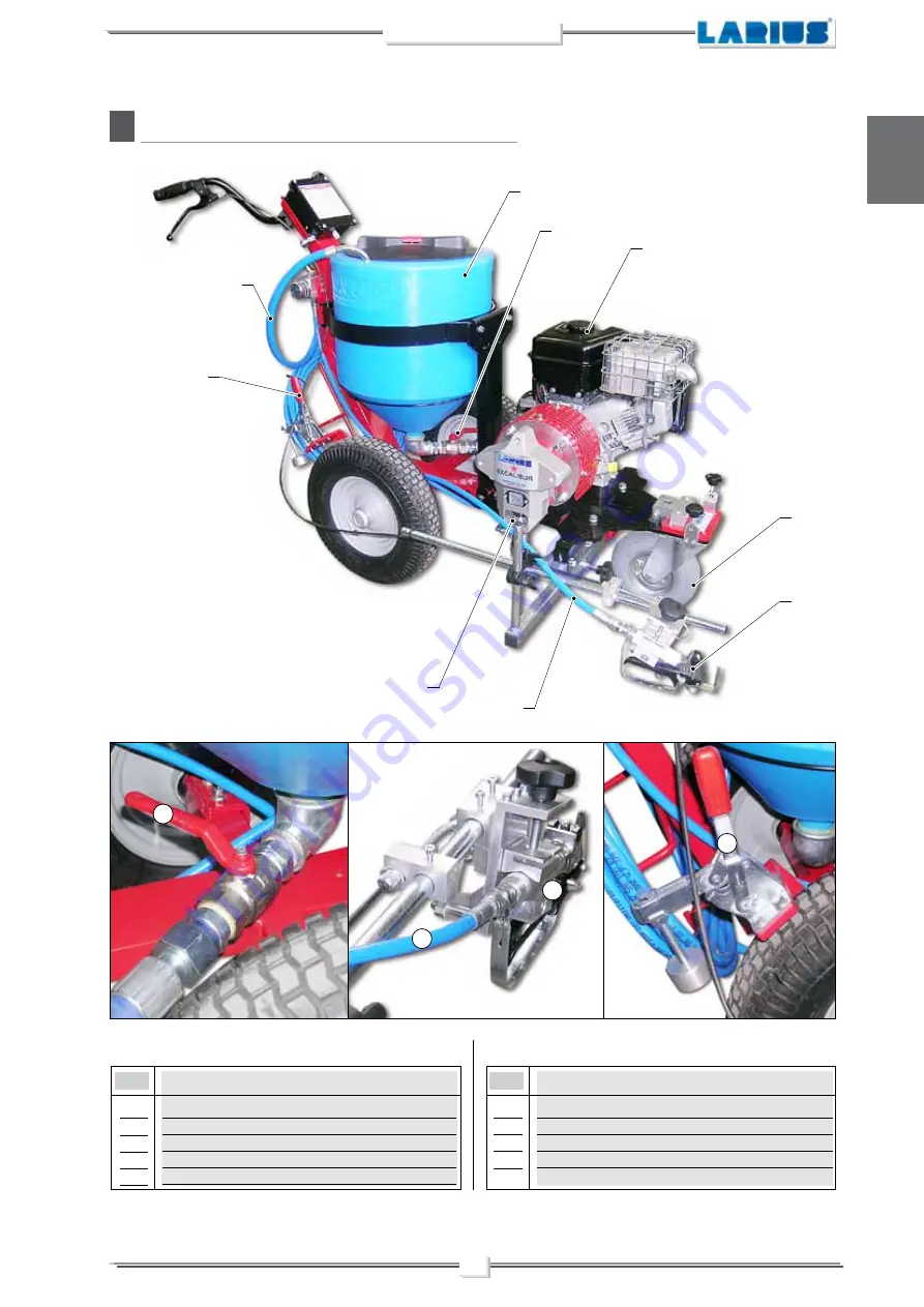
DESCRIPTION OF THE EQUIPMENT

POS.

1
2
3
4
5

lt. 50 tank
Recirculation tube
Suction intake valve
Product supply tube
Pumping group

Description

POS.

Description

Gun AT250
Pivoting wheel 
Gasoline tank
Brake 

6
7
8
9

Summary of Contents for Excalibur Liner

Page 1: ...OPERATING AND MAINTENANCE INSTRUCTION ENGLISH OPERATING AND MAINTENANCE INSTRUCTION P A I N T S P R A Y I N G E Q U I P M E N T Ed 013 10 14 STREET MARKING WITH PISTON PUMP ...

Page 2: ... manual without prior notice This manual is to be considered as an English language translation of the original manual in Italian The manufacturer shall bear no responsibility for any damages or inconveniences that may arise due to the incorrect translation of the instructions contained within the original manual in Italian ...

Page 3: ...p 14 REGULATIONS p 14 Adjusting the guns support arm p 14 WORKING p 15 Set up procedure p 15 Adjustment pump unit speed p 15 Spray adjustment p 15 CLEANING AT THE END OF THE WORK p 16 GENERAL MAINTENANCE p 17 Daily p 17 Periodically p 17 ROUTINE MAINTENANCE p 17 Check on the packing nut p 17 PROBLEMS AND SOLUTIONS p 18 CORRECT PROCEDURE OF DECOMPRESSION p 19 REPLACEMENT OF THE PUMPING GROUP S GASK...

Page 4: ...t indicates wound and finger squashing risk due to movable parts in the equipment Tenersi lontano dalle parti in movimento Do not use the equipment without the proper protection Before any inspection or maintenance of the equipment carry out the decompression procedure explained in this manual and prevent any risk of the equipment starting unexpectedly Report any risk of chemical reaction or explo...

Page 5: ...as well as every horizontal marking required by the highway code Airless marking has numerous proven benefits with respect to line markers with pressurised tanks which have been rendered obsolete by airless technology line markers Airless line marking guarantees Decreased Environmental Impact Decreased drying time This line marker utilises non premixed paints This allows it to achieve about 30 mor...

Page 6: ...4 EXCALIBUR LINER English Version 20L Version 50L ...

Page 7: ...ax pressure Airless spray gun Sizes of the furnished nozzles Tank Colours Manual line marking Applications Multi use sprayer Weight Lenght Height Width 4 kW 5 kW upon availability 2 l min 210 bar AT 250 11x40 13x40 15x40 50l 20l 1 series Medium road marking and maintenance series 105 kg A 160 cm B 110 cm C 90 cm ...

Page 8: ...ser pointer kit Ref 4506 Working spotlight SECTORS OF USE External or underground parking lots schools hotels airports supermarkets train stations subway stations ports External public areas Industrial and exhibition building zones Freeway service areas and service stations Pedestrian median lines intersections bicycle tracks reserved lanes Internal and external logistic area markings Playing fiel...

Page 9: ...9 2 1 3 5 4 6 8 6 7 9 C DESCRIPTION OFTHE EQUIPMENT POS 1 2 3 4 5 lt 50 tank Recirculation tube Suction intake valve Product supply tube Pumping group Description POS Description Gun AT250 Pivoting wheel Gasoline tank Brake 6 7 8 9 ...

Page 10: ...10 13 14 12 11 15 16 POS 10 11 12 13 Manometer Potentiometer for adjusting the operating pressure ON OFF switch Safety recirculation valve Description POS Description Plug Directional wheel lock release lever Gun operating lever 14 15 16 ...

Page 11: ...is used Thebehaviouroftheemployeesshallstrictly complywiththe Accident prevention AND ALSO ENVIRONMENTAL regulations in force in the countrywheretheplantisinstalledandused Read carefully and entirely the following instruc tions before using the product Please save these instructions in a safe place The unauthorised tampering replacement of one or more parts composing the machine the use of accesso...

Page 12: ...chloride Iftheseproductscomeintocontactwithaluminium parts can provoke dangerous chemical reactions with risk of corrosion and explosion IFTHE PRODUCTTO BE USED ISTOXIC AVOID INHALATION AND CONTACT BY USING PRO TECTION GLOVES GOGGLES AND PROPER FACE SHIELDS TAKE PROPER SAFETY MEASURES FOR THE PROTECTION OF HEARING IN CASE OF WORK NEAR THE PLANT Pump unit flexible tube connection Connect the pump u...

Page 13: ...ings threads Flexible tube and spray gun connection Connecttheflexibletube F5 totheconnector F6 ensuringto tighten the fittings the use of two wrenches is suggested STARTINGTHE MOTOR In order to start the motor proceed as follows Fill the gasoline tank F7 Open the fuel tap F8 and position it to ON Put the switch F9 ON I for the equipment Bring the accelerator lever F10 to about 1 2 of its run ...

Page 14: ...h diluent before sucking the product Lift the suction pipe and dip it into the solvent tank Clean the inside of the tank with a brush Open the product output tap F14 Pull the lever F11 for the first cold start up in position CHOKE Pull the start up cord F12 Start the motor following the indications provided in the chapter STARTINGTHE MOTOR Press the switch F15 of the equipment ON I Ensure the gun ...

Page 15: ...F18 Turn the pressure adjustment handle F17 clockwise to stop the pump Closed the recirculating safety valve F16 Turn pressure regulating knob F17 clockwise a little so that the machine idles Open the recirculating safety valve F16 Turn the pressure setting knob F17 clockwise to the CIR CULATION WASHING position drop symbol OPEN It re circulates back into the tank without spraying CLOSED It sprays...

Page 16: ...nual gun trigger lock and assemble the noz zle Mix and filter the product before using it For filtration use CLOSE MESH rif 214 and LARGE MESH rif 215 LARIUS METEX braids PRODUCT PREPARATION MAKE SURE THE PRODUCT IS SUITABLE TO BE USED WITH A SPRAY GUN Make sure the product to be used is compatible with the materials employed for manufacturing the equipment stainless steel and aluminium Because of...

Page 17: ...irculating safety valve when working at the maximum pressure available releasing the gun trigger sudden increases of pressure can occur In this case the recirculating safety valve opens automatically eliminating part of the product from the recirculating tube Then it closes so as to go back to the first working conditions Never point the spray gun at yourselves or at other people The contact with ...

Page 18: ...f the pump by bringing the handle I1 to its minimum position Fill the tank I2 with wash fluid Clean the walls of the tank with a brush Turn the pressure adjustment I1 handle slightly clockwise to make the machine function at minimum pressure pump activated Make sure the re circulation tube I3 is inserted into a con tainer and wait for clean wash fluid to come out of it Turn the pressure adjustment...

Page 19: ...ve before carrying out any maintenance Daily check the packing nut is tight in order to avoid wastes but not excessively to prevent the piston from seizing and the gaskets from wearing Use the lubricant K1 supplied ref 16325 to allow an easy sliding of the piston inside the gasket group Daily top up the packing nut At the start of each working day check that the ring nut is full of hydraulic oil R...

Page 20: ...ne The nozzle is partially clogged The product is too dense The filter of the gun butt is too fine The nozzle is worn The gaskets of the pumping group are worn Suction or delivery valve dirty Recirculating safety valve defective Ensure the On Off switch is on the on position and turn clockwise the pressure control knob Add gasoline Verify and replace it if necessary Open the drain valve to release...

Page 21: ...quipment is still under pressure after per forming the operations above described because ofthenozzleortheflexiblehoseclogged proceed as follows Loosen very slowly the gun nozzle Release the clamp Point the gun at the container of the product and press the trigger to release pressure Loosen very slowly the fitting of connection from the flexible hose to the gun Clean or replace the flexible hose a...

Page 22: ...lf adjusting Ifaleakoccursthey must be replaced N REPLACEMENT OFTHE PUMPING GROUP S GASKETS Pull the ignition belt N3 lightly until the piston rod has been brought to the lowest point of its stroke Remove the locking pin N4 using pliers N5 Unscrewthefixingringnut N6 totheendofthethreadusing a 45 mm spanner Unscrew the suction casing using a 32 mm spanner as illustrated If necessary remove the suct...

Page 23: ...pplied Turn anticlockwise as shown Use a 36 mm spanner to unscrew the pump unit as shown Remove the pump unit N12 from the foot valve N13 as shown Inspect the two parts separately PIT STOP MAINTENANCE Replacement of upper and lower gaskets 25 minutes REPLACINGTHE FOOT VALVE SEALS ReplacetheTeflongasket N14 locatedundertheballseating N15 Check that the surfaces of the ball seating N15 and the ball ...

Page 24: ...tem N17 from the pump unit housing N18 as shown Unscrew the gasket compression ring nut N19 completely All the gaskets in the unit must be replaced at the same time to allow the machine to work properly Remove the upper stainless steel female ring N20 as shown N15 N14 N16 N17 N18 N19 N20 N20 ...

Page 25: ...ide the pump unit housing as shown Remove the lower stainless steel male ring N21 as shown Fit the new gasket kit according to the component sequence shown in the figure Upper white Teflon 1 Grey polyethylene 2 N21 Waxed leather 3 Grey polyethylene 4 5 Lower whiteTeflon ...

Page 26: ... the stem N18 in a vice as shown Remove the Teflon O ring N23 and replace it with a new one N24 N22 N23 Waxed leather Code16155 Steel male ring Code 16108 Polyethylene grey Code 16124 PTFE white Code 16107 Steel female ring Code 16106 Polyethylene grey Code 16124 PTFE grey Code 16107 ...

Page 27: ...lace if necessary Usea10mmspannertounscrewandremovethestem N19 as indicated Remove the complete gasket kit N24 from the stem N18 as shown in order to replace it N18 N24 N18 Steel male ring Code 18644 Steel female ring Code 18645 PTFE white Code 16117 Polyurethane red Code 16114 PTFE White Code 16117 Polyethylene grey Code 16136 PTFE scraper ring Code 18648 ...

Page 28: ...ng N29 Ref 16126 with grease as shown Vaseline is recommended for this task Replace the grey polyethylene lipped gasket N25 for the valve piston Refit according to the assembly order and the alignment of the lip as shown Check the surfaces of the ball N26 and ball seating N27 and replace both if damaged Assemble the components as shown Lubricate the gaskets N28 and the stem Vaseline is recommended...

Page 29: ...d previously complete a full stroke as shown Usethepin N11 suppliedtotightenthegasketcompression ring nut N10 Close this until it is fully touching without forcing CORRECT POSITIONING OFTHE PUMP UNIT Once the unit has been refitted proceed as follows Checkthepositionoftheconrod whichshouldbepositioned at its lower stopping point Puttheentirepumpunit N9 insidethereductioncover N32 as shown N31 N30 ...

Page 30: ...N33 Check that the closing spring N35 in the con rod N33 goes into the pin seating when closed as shown Screw the entire pump unit N9 inside the reduction cove The reference value see drawing must be 18 mm The maximum tolerance accepted for correct ope ration is 21 mm maximum and 16 mm minimum Use a gauge to measure the gap between the base of the template and the start of the tightening groove N9...

Page 31: ...the exploded diagram for the pump unit and invert the order used for disassembly Once the unit has been positioned correctly tighten the lock nut N36 hard against the front template To tighten use a 45 mm spanner Close the inspection cover N2 again N36 N2 ...

Page 32: ...oup page 31 O Z Accessories page 43 O U Complete box Ref 4896 page 40 O Q Complete Excalibur Liner Unit Ref 4877 page 36 O S Complete 50L tank REF 4895 page 38 O T Complete 20L tank REF 4890 page 39 O W Re circulationunitcomple te with cover Ref 4893 page 42 O V Complete box transfor mer Rif 4845 page 41 SPARE PARTS SPARE PARTS ...

Page 33: ...g Complete lower seals Complete foot valve Complete sleeve Complete piston 16109 16127 16105 96206 18640 16126 18642 16120 91018 18643 18641 18652 16130 18648 18651 18655 18649 18650 1 2 3 4 5 6 7 8 9 10 11 12 13 14 15 16 17 18 Code Description Complete gasket kit upper and lower cod 18855 Pumping maintenance kit cod 40106 COMPLETE PUMPING GROUP WARNING Always indicate code and quantity for each p...

Page 34: ...114 PTFE White Code 16177 Polyethylene grey Code 16136 Code 16132 Code 16105 PTFE scraper ring Code 18648 Waxed leather Code16155 Steel male ring Code 16108 Polyethylene grey Code 16124 PTFE white Code 16107 Steel female ring Code 16106 Polyethylene grey Code 16124 PTFE grey Code 16107 U P P E R S E A L S L O W E R S E A L S Code 16133 Code 18651 ...

Page 35: ...876 WARNING Always indicate code and quantity for each part required Pos Pos Complete steering unit Screw Screw Washer Base Nut Spring Wire stopper Pin Washer Screw 4876 4735 95068 330058 4737 3637 11205 2 4253 4875 5339 4739 Code Description Code Description 1 2 3 4 5 6 7 8 9 10 ...

Page 36: ...ish 16 15 12 13 14 17 26 25 27 18 22 21 28 29 30 32 31 33 26 25 24 23 34 11 1 8 38 2 4 3 5 31 10 7 35 9 6 36 37 19 20 42 39 40 41 Q COMPLETETELAIO REF COD 4874 WARNING Always indicate code and quantity for each part required ...

Page 37: ...Frame Washer Plate Washer Complete spray gun support unit Complete spray gun AT250 Fast Clean small Liner accessory Compensation tube 3 16 10m 4874 4256 4463 4865 4464 4866 7043 4873 81032 4825 4868 4867 8371 4492 4461 4869 4450 4447 4490 3637 34009 81032 4429 4870 4265 33005 95068 4260 4871 4449 4872 32005 8037 4255 91062 4864 32005 4824 34009 4448 11200 4833 35018 Code Description Code Descripti...

Page 38: ...XCALIBUR LINER English 27 8 9 10 18 11 12 17 16 4 3 14 15 13 5 6 4 3 2 1 26 25 24 23 22 21 20 3 19 7 R COMPLETE EXCALIBUR LINER UNIT REF 4877 WARNING Always indicate code and quantity for each part required ...

Page 39: ...ion damping pad Motor Tab Flange Tightening rod Screw Cover Bush Tab Screw Screw Pinion Screw Excalibur Liner reduction unit 4877 96080 700711 34009 3637 4879 4880 4416 4882 4883 4884 95158 54004 32005 700150 4889 18188 4887 4886 96031 4888 4885 30656 18192 54004 4881 21556 4878 Code Description Code Description 1 2 3 4 5 6 7 8 9 10 11 12 13 14 15 16 17 18 19 20 21 22 23 24 25 26 27 ...

Page 40: ...and quantity for each part required Pos Pos Complete 50LTank Cover Filter Support 50L Tank Support Nut Washer Screw Support Seal Union Elbow Complete suction output system 4895 18249 1 85014 18231 18249 18246 52017 34009 901568 4894 96099 95032 18215 16676 Code Description Code Description 1 2 3 4 5 6 7 8 9 10 11 12 13 ...

Page 41: ... indicate code and quantity for each part required Pos Pos Complete 20LTank Screw Nut Ring Rubber Cover 20l Tank Belt Screw Base Cover complet Complete suction output system 4890 4314 52017 4308 4309 4109 4064 4274 69014 4250 4111 16676 Code Description Code Description 1 2 3 4 5 6 7 8 9 10 11 ...

Page 42: ...F 4896 WARNING Always indicate code and quantity for each part required Pos Pos Complete box Screw Switch ON OFF Potentiometer Closure plate Nut Washer Warning stickers 4896 91062 5933 30549 4923 8042 32005 16850 Code Description Code Description 1 2 3 4 5 6 ...

Page 43: ...4 V COMPLETE BOXTRASFORMER REF 4845 WARNING Always indicate code and quantity for each part required Pos Pos Complete box transformer Nut Washer Screw Transformer box 4845 8042 32005 91062 4846 Code Description Code Description 1 2 3 4 ...

Page 44: ...uired Pos Pos Re circulation unit complete with cover Cover Sensor Tenuta Or Screw Washer Plug Or Seal Filter Sieve Union Union Base Valve Washer Screw Cable fastener Copper gasket Warning stickers 4893 4891 18692 18689 33004 33005 18580 18622 16205 18627 96206 18614 4892 16400 32005 91062 18871 18684 16854 Code Description Code Description 1 2 3 4 5 6 7 8 9 10 11 12 13 14 15 16 17 ...

Page 45: ...0 MESH Code 271 FILTER 60 MESH Code 16200 LINE FILTER Code 16675 Suction system Code 4405 PEARLIZED REFLECTING PAINT DISTRIBUTION KIT PISTON GUNSTOCK FILTERS Code 11039 Green 30M Code 11038 White 60M Code 11037 Yellow 100M Code 11019 Red 200M Code 16802 FILTER 30 MESH Cod 11250 AT 250 1 4 Cod 11200 AT 250 M16x1 5 ...

Page 46: ...27 40 SFC27 60 SFC27 80 SFC29 20 SFC29 40 SFC29 60 SFC29 80 SFC31 40 SFC31 60 SFC31 80 SFC33 40 SFC33 60 SFC33 80 SFC39 40 SFC39 60 SFC39 80 SFC43 40 SFC43 60 SFC43 80 SFC51 40 SFC51 60 SFC51 80 TOP SPRAYING CLEAN TOP SPRAYING CLEANTIP nozzles code TSC 7 20 TSC 7 40 TSC 9 20 TSC 9 40 TSC 11 20 TSC 11 40 TSC 13 20 TSC 13 40 TSC 13 60 TSC 15 20 TSC 15 40 TSC 15 60 TSC 17 20 TSC 17 40 TSC 17 60 TSC 1...

Page 47: ...TELESCOPIC PAINT ROLLER complete with n 1 Roller with extra long fiber n 1 Roller with long fiber n 1 Roller with medium fiber Flexible hose mt 2 3 16 M16x1 5 ANTIPULSATIONS 1 4 M16x1 5 pressure max 250 bar Art 35013 5 mt Art 35014 7 5 mt Art 35017 10 mt Art 18026 15 mt HIGH PRESSURE HOSE 3 8 M16x1 5 pressure max 425 bar Art 18063 7 5 mt Art 18064 10 mt Art 18065 15 mt ANTISTATIC HOSE 3 16 M16x1 5...

Page 48: ...AGON LINER SEMOVENTE LINE STRIPERS 23801CALOLZIOCORTE LECCO ITALY ViaAntonioStoppani 21 Tel 39 0341 62 11 52 Fax 39 0341 62 12 43 E mail larius larius com Internet http www larius com MANUFACTURER DIRECT LINE Tel 39 0341 621256 Fax 39 0341 621234 CUSTOMERS TECHNICAL SERVICE VIKING LINER ...

Reviews: