background image

Configuring the UDS Using Web Manager 

UDS200 User Guide


17 

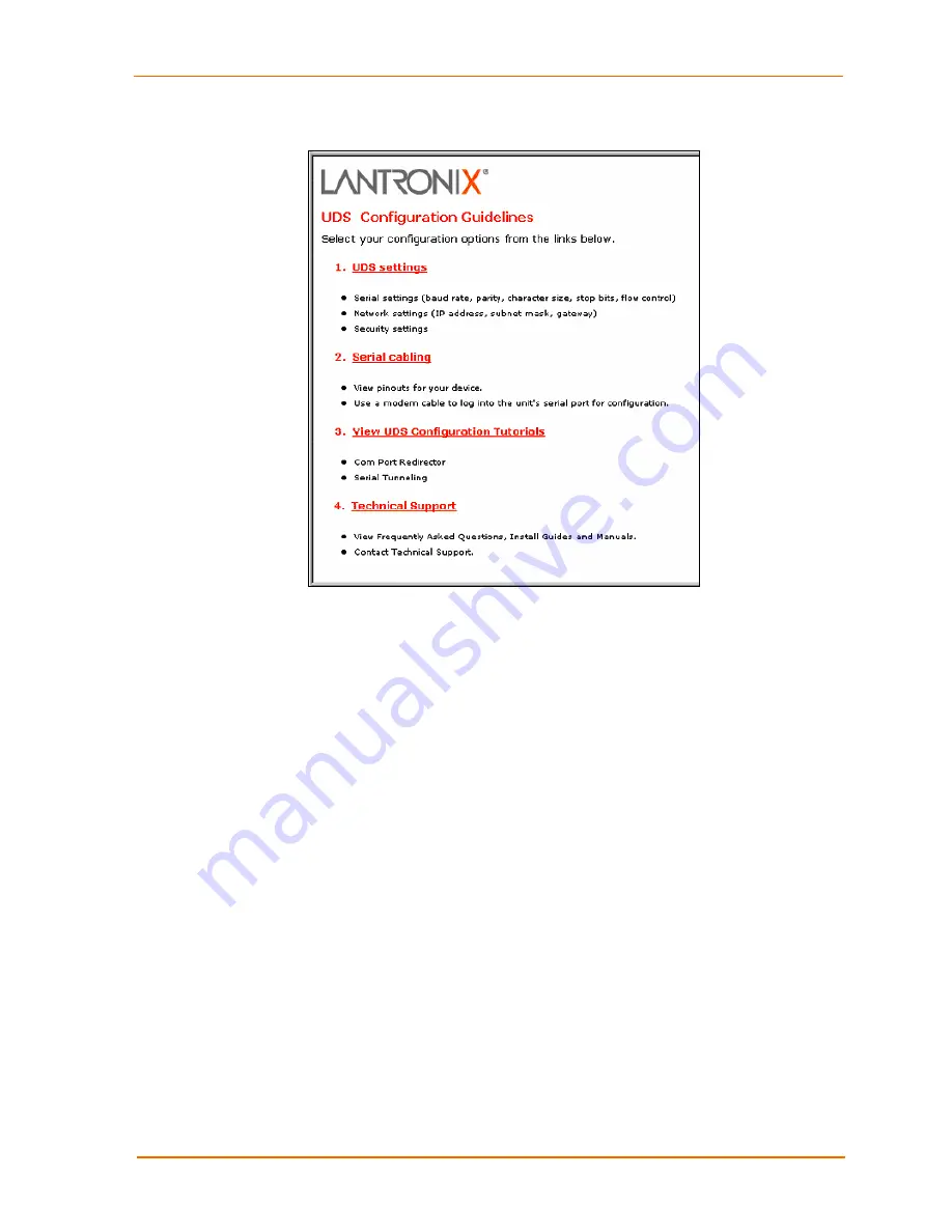
Figure 4-2. UDS Configuration Guidelines Page 


‹


UDS settings

 opens a configuration window to configure the UDS200, as 

shown in Figure 4-3. 

‹


Serial cabling

 lets you view pinouts for the UDS serial port. 

‹


View UDS Configuration Tutorials

 provides step-by-step instructions for 

configuring serial tunneling and the Com Port Redirector. 

‹


Technical Support

 lets you download the latest firmware for your UDS and 

view documentation. 


Summary of Contents for UDS200

Page 1: ...Part Number 900 303 Revision D December 2007 UDS200 User Guide ...

Page 2: ......

Page 3: ...ential area is likely to cause interference in which case the user at his or her own expense will be required to take whatever measures may be required to correct the interference Note This product has been designed to comply with the limits for a Class A digital device pursuant to Part 15 of FCC Rules These limits are designed to provide reasonable protection against such interference when operat...

Page 4: ..._________________________________ 13 IP Address_____________________________________________________________ 13 Assigning the IP Address and Related Network Settings ____________________ 14 DeviceInstaller__________________________________________________________ 14 Serial Port Login ________________________________________________________ 15 4 Configuring the UDS Using Web Manager 16 Accessing We...

Page 5: ..._______ 33 TCP Keepalive time in s__________________________________________________ 34 ARP Cache timeout in s __________________________________________________ 34 Security Settings ___________________________________________________ 34 Disable SNMP _________________________________________________________ 34 SNMP Community Name _________________________________________________ 34 Disable Telnet ...

Page 6: ...nnector Pinouts _______________________________________________ 51 Null Modem Cable ______________________________________________________ 51 A Alternative Ways to Assign an IP Address 53 DHCP ________________________________________________________________ 53 AutoIP ________________________________________________________________ 53 BOOTP __________________________________________________________...

Page 7: ... Sending Firmware to another Unit 39 Figure 6 3 Firmware Upgrade Screen Display 39 Figure 7 1 Entering Monitor Mode Using the Network 41 Figure 10 1 Serial Interface 50 Figure 10 2 DB9 Male RS232 Serial DTE Connector 50 Figure 10 3 Network Interface 51 Figure 10 4 RJ45 Ethernet Connector 51 Figure 10 5 Null Modem Cable Lantronix Part No 500 164 52 Tables Table 5 1 Netmask Examples 23 Table 5 2 Int...

Page 8: ...t connection through the network or a terminal or terminal emulation program through the serial port Details the settings that you must configure 6 Updating Firmware Provides instructions for obtaining the latest firmware and updating the UDS200 7 Using Monitor Mode Provides instructions for accessing and using the command line interface to monitor the network and diagnose problems 8 Troubleshooti...

Page 9: ...ation The following guide is available on the product CD or the Lantronix Web site www lantronix com DeviceInstaller User Guide Provides instructions for using the Windows based utility to configure the UDS and other Lantronix device servers CD and web site ...

Page 10: ...pply UPS management units Telecommunications equipment Data display devices Virtually any asynchronous RS 232 RS422 or RS485 device Application Examples Using a method called serial tunneling the UDS200 encapsulates serial data into packets and transports them over Ethernet Using two UDS200 units connected by a network virtual serial connections can extend across a facility or around the world The...

Page 11: ... Transmission Control Protocol TCP to assure that no data is lost or duplicated and everything sent to the connection arrives correctly at the target Other protocols supported are ARP UDP TCP ICMP Telnet TFTP AutoIP DHCP HTTP and SNMP for network communications TCP UDP and Telnet for connections to the serial port TFTP for firmware updates IP for addressing routing and data block handling over the...

Page 12: ...ttings on the UDS200 using a Graphical User Interface GUI on a PC attached to a network See DeviceInstaller on page 14 Web Manager Through a web interface configure the UDS200 settings using the Lantronix Web Manager See 4 Configuring the UDS Using Web Manager Serial and Telnet Ports There are two approaches to accessing Setup Mode making a Telnet connection to the network port 9999 or connecting ...

Page 13: ...in order Refer to the numbers in the previous figure 1 Connect a serial device to your unit See 10 Connections and Pinouts for more information about what kinds of device attachments the unit supports 2 Connect an Ethernet cable to the 10 100 port 3 Supply power to your unit using the power supply that was included in the packaging Note The required input voltage is 9 30 VDC or 9 24 VAC 2W maximum...

Page 14: ...r generally provides the IP address subnet mask and gateway Note The factory default IP address is 0 0 0 0 to enable DHCP BOOTP and AutoIP When the units boots it sends a DHCP broadcast to try and get an IP address If it receives no reply from a DHCP server the UDS tries BOOTP If the UDS does not receive a response from BOOTP it reverts to an AutoIP address IP Address _______ _______ _______ _____...

Page 15: ... backslash deviceinstaller exe e g E deviceinstaller exe 3 Click the DeviceInstaller button The installation wizard window displays 4 Respond to the installation wizard prompts When prompted to select an installation type select Typical Assigning the IP Address and Network Class 1 Click the Start button on the Task Bar and select Programs Æ Lantronix Æ DeviceInstaller Æ DeviceInstaller The DeviceI...

Page 16: ... click the Telnet icon The Setup Mode window displays Continue with 5 Configuring the UDS Using Telnet or the Serial Port Serial Port Login To assign the IP address and other network settings using a serial connection follow these steps 1 Connect a console terminal or a PC running a terminal emulation program to the unit s serial port The default serial port settings are 9600 baud 8 bits no parity...

Page 17: ...memory NVRam and is retained without power You can change the configuration at any time The unit performs a reset after the configuration has been changed and stored Note When configuring the UDS200 note that it does not support 2 stop bits for port 2 Accessing Web Manager If your unit already has an IP address you can log into it using a standard Web browser with Java enabled Note You can also ac...

Page 18: ...on window to configure the UDS200 as shown in Figure 4 3 Serial cabling lets you view pinouts for the UDS serial port View UDS Configuration Tutorials provides step by step instructions for configuring serial tunneling and the Com Port Redirector Technical Support lets you download the latest firmware for your UDS and view documentation ...

Page 19: ... menu pushbuttons to navigate to sub pages where you can configure server settings Note Explanations of all parameters are in 5 Configuring the UDS Using Telnet or the Serial Port 2 When you are finished click the Update Settings button to save your settings For example to enter server properties 1 Click the Server Properties button The Server Properties section of the Web page displays 2 Confirm ...

Page 20: ...a password to prevent unauthorized access to the Setup Mode using a Telnet connection to port 9999 The password is limited to four characters An enhanced password setting of 16 characters is available under Security Settings in Setup Mode Note No password is required to access the Setup Mode window using a serial connection 4 Click the Update Settings button ...

Page 21: ...nit performs a reset after the configuration has been changed and stored This chapter provides instructions on using Setup Mode and detailed explanations of the configuration settings Note When configuring the UDS200 note that it does not support 2 stop bits for port 2 Using a Telnet Connection To configure the unit over the network establish a Telnet connection to port 9999 Note You can also esta...

Page 22: ...3 Select an option on the menu by entering the number of the option at the Your choice prompt and pressing Enter 4 To enter a value for a parameter type the value and press Enter or to confirm a current value just press Enter 5 When you are finished save the new configurations option 9 The unit reboots ...

Page 23: ...te The easiest way to enter Setup Mode is to hold down the x key on your keyboard while powering up the unit 3 Select an option on the menu by entering the number of the option at the Your choice prompt and pressing Enter 4 To enter a value for a parameter type the value and press Enter or to confirm a default value just press Enter 5 When you are finished save the new configuration option 9 The u...

Page 24: ...Host Bits 255 255 255 252 2 255 255 255 248 3 255 255 255 240 4 255 255 255 224 5 255 255 255 192 6 255 255 255 128 7 255 255 255 0 8 255 255 254 0 9 255 255 252 0 10 255 255 248 0 11 255 128 0 0 23 255 0 0 0 24 Change Telnet configuration password Setting the Telnet configuration password prevents unauthorized access to Setup Mode using a Telnet connection to port 9999 or using Web pages The pass...

Page 25: ...cientific calculator such as the one available in Windows For more information see B Binary to Hexadecimal Conversions Select 1 from the Change Setup menu to define how the serial port responds to network and serial communications The rest of this section describes the configurable settings within the Channel configuration menu Current values display in parentheses Figure 5 5 Channel 1 Configurati...

Page 26: ...000 78 RS 485 2 Wire 8 bit No Parity 1 stop bit 0100 1111 4F RS 422 8 bit Odd Parity 1 stop bit 0101 1101 5D Flow Flow control sets the local handshake method for stopping serial input output Use the following table to select flow control options Table 5 4 Flow Control Options Flow Control Option Hex No flow control 00 XON XOFF flow control 01 Hardware handshake with RTS CTS lines 02 XON XOFF pass...

Page 27: ...it is in a passive mode or when you are using UDP instead of TCP Connect Mode Connect Mode defines how the unit makes a connection and how it reacts to incoming connections over the network Enter Connect Mode options in hexadecimal notation Note To look up hex values see B Binary to Hexadecimal Table 5 5 Connect Mode Options Connect Mode Option Bit 7 6 5 4 3 2 1 0 Incoming Connection Never accept ...

Page 28: ...he IP address and uses the internally stored remote IP address to provide the most significant bytes of the IP address If the IP address entered is 0 0 0 0 0 the device server enters Monitor Mode For example if the remote IP address already configured in the unit is 129 1 2 3 then an example command string would be C3 7 This would connect to 129 1 2 3 and port 7 You may also use a different ending...

Page 29: ...lete modify or add an entry select Yes If you enter an IP address of 0 0 0 0 that entry and all others after it are deleted 3 After completing the hostlist repeat the previous step if necessary to edit the hostlist again 4 For Retrycounter enter the number of times the Lantronix unit should try to make a good network connection to a hostlist entry that it has successfully ARPed 5 For Retrytimeout ...

Page 30: ...it still accepts network TCP connections to the serial port if Connect Mode is set to C6 no echo D6 echo with full verbose or D7 echo with 1 character response Echo Refers to the echo of all of the characters entered in command mode it does not mean to echo data that is transferred Quiet Mode no echo refers to the modem not sending an answer to the commands received or displaying what was typed Fu...

Page 31: ...ort n 0 disables the ability to make a connection from the network to the serial port n 1 9 enables the ability to make a connection from the network to the serial port n 1 9 is invalid ATEn Enables or disables character echo and responses n 0 disables character echo and responses n 1 enables character echo and responses ATVn Enables 1 character response or full verbose n 0 enables 1 character res...

Page 32: ...the disconnection 4 When there is a network connection to or from the serial port the state LED turns off instead of blinking 5 When Ctrl D or Hex 04 is detected the connection is dropped Both Telnet mode and Disconnect with EOT must be enabled for Disconnect with EOT to function properly Ctrl D is only detected going from the serial port to the network Flush Mode Flush Mode buffer flushing contro...

Page 33: ...wo 1 0 Send Characters 2 Byte Send Character Sequence 1 Send Immediately After Send chars 1 Idle Time Idle time to Force transmit defines how long the unit waits before sending accumulated characters This wait period is between characters If there is an idle period between characters equal to the Force transmit set the UDS packages the serial data currently in the buffer and sends it to the networ...

Page 34: ...specific protocol characters on the serial line for example ETX EOT Setting the first SendChar to 00 disables the recognition of the characters Alternatively the unit can interpret two characters as a sequence see Pack Control on page 32 Telnet Terminal Type This parameter displays only if the terminal type option is enabled in Disconnect Mode If this option is enabled use the terminal name for th...

Page 35: ... an entry in this table Security Settings Change these settings using Telnet or serial connections only not Web Manager Note We recommend that you set security over the dedicated network or over the serial setup If you set security over the network Telnet 9999 someone else could capture these settings Caution Disabling both Telnet Setup and Port 77FE prevents users from accessing the Setup Mode fr...

Page 36: ...nstaller Web Manager and custom programs use Port 77FE to configure the unit remotely If required disable this capability for security purposes The default setting is the N No option which enables remote configuration As a result configure the unit by using DeviceInstaller Web Manager Telnet or serial configuration The Y Yes option disables remote configuration and Web Manager Note the Y Yes optio...

Page 37: ... always accept incoming connection no active connection startup Hostlist retry counter 3 Hostlist retry timeout 250 msec Start character 0x0D CR All other settings 0 Expert Settings Defaults TCP keepalive 45 seconds ARP cache timeout 600 seconds Security Settings Defaults SNMP Enabled SNMP community name public Telnet setup Enabled TFTP download Enabled Port 77FEh Enabled Web Server Enabled ECHO D...

Page 38: ...tronix com or ftp ftp lantronix com and store them in a subfolder on your computer 2 Click the Start button on the Task Bar and select Programs Æ Lantronix Æ DeviceInstaller Æ DeviceInstaller The DeviceInstaller window displays 3 Click the Search the network for devices icon The Search Network window displays 4 Once located by DeviceInstaller highlight the device in the device list and click the U...

Page 39: ...ROM to the unit to upgrade the unit s internal operational code and cbx cob to upgrade its internal Web interface Note TFTP requires the ROM binary version of the unit s internal operational code 2 Make sure the Put and Binary options at the top of the window are selected 3 Enter the full path of the firmware file in the Source File field 4 In the Destination File field type U2 for the internal op...

Page 40: ...ing procedure is for using the HyperTerminal software application This procedure takes about 10 minutes Note Do not switch off the power supply during the update A loss of power while reprogramming will result in a corrupt program image and a nonfunctional unit To download firmware from a computer using the unit s serial port 1 Enter Monitor Mode using the serial port see 7 Using Monitor Mode 2 Do...

Page 41: ...Updating Firmware UDS200 User Guide 40 Note You can only update your unit s internal Web interface using TFTP or DeviceInstaller ...

Page 42: ...ation settings 1 Do one of the following To enter Monitor Mode with network connections type xx1 or zzz not three x keys as you did before To enter Monitor Mode without network connections type xx2 or yyy A 0 prompt indicates that you have successfully entered Monitor Mode Entering Monitor Mode Using the Network To enter Monitor Mode using a Telnet connection 1 First establish a Telnet session The...

Page 43: ... x as hex records SC x x x x Send Configuration Sets configuration of unit with IP address x x x x from hex records PI x x x x Ping Pings unit with IP address x x x x to check device status AT ARP Table Shows the unit s ARP table entries TT TCP Connection Table Shows all incoming and outgoing TCP connections NC Network Connection Shows the unit s IP configuration RS Reset Resets the unit s power Q...

Page 44: ...ions power cable network cable and serial cable are secure Note Some unexplained errors might be caused by duplicate IP addresses on the network Make sure that your unit s IP address is unique LEDs The UDS200 contains the following LEDs which may help you diagnose problems Power 10 Mbps Link Activity green 100 Mbps Link Activity green Diagnostics red Status Channel 1 green Status Channel 2 green S...

Page 45: ... diagnostic information sent out the serial port Table 8 2 Problems and Error Messages Problem Message Reason Solution When you issue the ARP S command in Windows The ARP entry addition failed 5 message displays Your currently logged in user does not have the correct rights to use this command on this PC Have someone from your IT department log you in with sufficient rights When you attempted to a...

Page 46: ...ed into the network properly Make sure that the Link LED is lit If the Link LED is not lit then the UDS is not properly plugged into the network When you try to assign an IP with DeviceInstaller you get the following message No device was found at this hardware address The cause is most likely one of the following The Hardware address you specified is incorrect The device is not physically connect...

Page 47: ...m that Caps Lock is not on You can ping the UDS but not Telnet to the UDS on port 9999 There may be an IP address conflict on your network You are not Tenting to port 9999 The Telnet configuration port 9999 is disabled within the UDS security settings The unit may have the correct IP address but an incorrect gateway address Turn the UDS off and then issue the following commands at the DOS prompt o...

Page 48: ...UDS See the full list of Connect Mode hexadecimals in B Binary to Hexadecimal When connecting to Web Manager within the UDS the message No Connection With The UDS displays Your computer is not able to connect to port 30718 77FEh on the UDS Make sure that port 30718 77FEh is not blocked with any router that you are using on the network Also make sure that port 77FEh is not disabled within the Secur...

Page 49: ...ion on the first screen shown when you Telnet to the device and type show Description of the problem Debug report stack dump if applicable Status of the unit when the problem occurred please try to include information on user and network activity at the time of the problem ...

Page 50: ...ork Interface 10 100 RJ45 Ethernet Power Supply External adapter included 120 VAC USA 100 240 VAC Universal with regional connectors Power Input 9 30 VDC or 9 24 VAC 2W maximum Dimensions UDS200 Height 2 3 cm 0 9 in Width 7 3 cm 2 87 in Depth 9 5 cm 3 74 in Weight UDS200 0 35 Kg 0 8 lbs Temperature Operating range 5 to 50 C 41 to 122 F Storage range 40 to 66 C 40 to 151 F Relative Humidity Operati...

Page 51: ...RS 232 serial standards up to 115 Kbps Figure 10 1 Serial Interface Serial Connector Pinouts The unit s Male DB9 connector provides an RS 232C interface as would be found on most modern computers The default serial port settings are 9600 baud 8 bits no parity 1 stop bit no flow control Figure 10 2 DB9 Male RS232 Serial DTE Connector Male DB9 Serial Ports ...

Page 52: ...et Connector Pinouts Figure 10 4 RJ45 Ethernet Connector Null Modem Cable When attaching the DB9 of the UDS to the DB9 com port on a PC use a null modem cable Lantronix Part No 500 164 The figure below shows the pinouts for a DB9 to DB9 null modem cable To configure the UDS using the DB9 serial port you only need to pinout the TXD RXD and GND signals RJ45 Ethernet Port Power Plug ...

Page 53: ...UDS200 User Guide Connections and Pinouts 52 Figure 10 5 Null Modem Cable Lantronix Part No 500 164 ...

Page 54: ...omatically enables Auto IP within the unit AutoIP is an alternative to DHCP that allows hosts to obtain an IP address automatically in smaller networks that may not have a DHCP server A range of IP addresses from 169 254 0 1 to 169 254 255 1 has been explicitly reserved for AutoIP enabled devices Do not use this range of Auto IP addresses over the Internet If your unit cannot find a DHCP server an...

Page 55: ...han its own 2 If you are using Windows 95 type ARP A at the DOS command prompt to verify that there is at least one entry in the ARP table If the local machine is the only entry ping another IP address on your network to build a new entry in the ARP table the IP address must be a host other than the machine on which you are working Once there is at least one additional entry in the ARP table use t...

Page 56: ...s Flush Mode Buffer Flushing Options Interface Mode Options Pack Control Options Converting Binary to Hexadecimal Following are two simple ways to convert binary numbers to hexadecimal notation Conversion Table Hexadecimal digits have values ranging from 0 to F which are represented as 0 9 A for 10 B for 11 etc To convert a binary value for example 0100 1100 to a hexadecimal representation treat t...

Page 57: ...o use a scientific calculator such as the one available on Windows operating systems For example 1 On the Windows Start menu click ProgramsÆAccessoriesÆCalculator 2 On the View menu select Scientific The scientific calculator displays 3 Click Bin Binary and type the number you want to convert 4 Click Hex The hexadecimal value displays ...

Page 58: ... active startup 40 With DSR None quiet Any character 41 With DSR None quiet Active DSR 42 With DSR None quiet CR 0x0D 43 With DSR None quiet Manual connection 44 With DSR None quiet Autostart 45 With DSR None quiet UDP 4C With DSR Character No active startup 50 With DSR Character Any character 51 With DSR Character Active DSR 52 With DSR Character CR 0x0D 53 With DSR Character Manual connection 54...

Page 59: ...Hostlist 62 With DSR None quiet CR 0x0D Hostlist 63 With DSR None quiet Manual connection Hostlist N A With DSR None quiet Autostart Hostlist 65 With DSR None quiet UDP Hostlist N A With DSR Character No active startup Hostlist N A With DSR Character Any character Hostlist 71 With DSR Character Active DSR Hostlist 72 With DSR Character CR 0x0D Hostlist 73 With DSR Character Manual connection Hostl...

Page 60: ...ation Connect Mode Options for Modem Emulation Accept Incoming Connections Response Hex Never Echo 16 Never Without echo 6 Never 1 character response 7 With DSR Echo 56 With DSR Without echo 46 With DSR 1 character response 47 Unconditionally Echo D6 Unconditionally Without echo C6 Unconditionally 1 character response C7 ...

Page 61: ...able Enable Enable Enable E0 Enable Enable Enable Enable Enable F0 Enable Enable 1 Enable Enable Enable 11 Enable Enable Enable 21 Enable Enable Enable Enable 31 Enable Enable Enable 41 Enable Enable Enable Enable 51 Enable Enable Enable Enable 61 Enable Enable Enable Enable Enable 71 Enable Enable Enable 81 Enable Enable Enable Enable 91 Enable Enable Enable Enable A1 Enable Enable Enable Enable ...

Page 62: ...le Enable E8 Enable Enable Enable Disable Enable F8 Disable Enable 9 Enable Disable Enable 19 Disable Enable Enable 29 Enable Disable Enable Enable 39 Enable Disable Enable 49 Enable Enable Disable Enable 59 Enable Disable Enable Enable 69 Enable Enable Disable Enable Enable 79 Enable Disable Enable 89 Enable Enable Disable Enable Enable 99 Enable Disable Enable Enable A9 Enable Enable Disable Ena...

Page 63: ...Enable B0 Disconnect Enable C0 Active connection Disconnect Enable D0 Passive connection Disconnect Enable E0 Active connection Passive connection Disconnect Enable F0 Active connection 1 Active connection Active connection 11 Passive connection Active connection 21 Active connection Passive connection Active connection 31 Disconnect Active connection 41 Active connection Disconnect Active connect...

Page 64: ...tion 72 Passive connection Enable 82 Active connection Passive connection Enable 92 Passive connection Passive connection Enable A2 Active connection Passive connection Passive connection Enable B2 Disconnect Passive connection Enable C2 Active connection Disconnect Passive connection Enable D2 Passive connection Disconnect Passive connection Enable E2 Active connection Passive connection Disconne...

Page 65: ...t Active connection Passive connection Enable F3 Disconnect 4 Active connection Disconnect 14 Passive connection Disconnect 24 Active connection Passive connection Disconnect 34 Disconnect Disconnect 44 Active connection Disconnect Disconnect 54 Passive connection Disconnect Disconnect 64 Active connection Passive connection Disconnect Disconnect 74 Disconnect Enable 84 Active connection Disconnec...

Page 66: ...onnect Active connection Disconnect Enable D5 Passive connection Disconnect Active connection Disconnect Enable E5 Active connection Passive connection Disconnect Active connection Disconnect Enable F5 Passive connection Disconnect 6 Active connection Passive connection Disconnect 16 Passive connection Passive connection Disconnect 26 Active connection Passive connection Passive connection Disconn...

Page 67: ...nection Disconnect 47 Active connection Disconnect Active connection Passive connection Disconnect 57 Passive connection Disconnect Active connection Passive connection Disconnect 67 Active connection Passive connection Disconnect Active connection Passive connection Disconnect 77 Active connection Passive connection Disconnect Enable 87 Active connection Active connection Passive connection Disco...

Page 68: ...ansmit Send Immediately after Sendcharacter Hex 1 Byte Sequence No 12ms 0 1 Byte Sequence No 52ms 1 1 Byte Sequence No 250ms 2 1 Byte Sequence No 5sec 3 1 Byte Sequence 1 12ms 4 1 Byte Sequence 1 52ms 5 1 Byte Sequence 1 250ms 6 1 Byte Sequence 1 5sec 7 1 Byte Sequence 2 12ms 8 1 Byte Sequence 2 52ms 9 1 Byte Sequence 2 250ms A 1 Byte Sequence 2 5sec B 2 Byte Sequence No 12ms 10 2 Byte Sequence No...

Page 69: ...1 52ms Yes 25 1 Byte Sequence 1 250ms Yes 26 1 Byte Sequence 1 5sec Yes 27 1 Byte Sequence 2 12ms Yes 28 1 Byte Sequence 2 52ms Yes 29 1 Byte Sequence 2 250ms Yes 2A 1 Byte Sequence 2 5sec Yes 2B 2 Byte Sequence No 12ms Yes 30 2 Byte Sequence No 52ms Yes 31 2 Byte Sequence No 250ms Yes 32 2 Byte Sequence No 5sec Yes 33 2 Byte Sequence 1 12ms Yes 34 2 Byte Sequence 1 52ms Yes 35 2 Byte Sequence 1 2...

Page 70: ...4 1995 Electrical Fast Transient Test IEC61000 4 5 1995 Power Supply Surge Test IEC61000 4 6 1996 Conducted Immunity Test IEC61000 4 8 1993 Magnetic Field Test IEC61000 4 11 1994 Voltage Dips Interrupts Test L V D Directive 73 23 EEC Supplementary Information This Class A digital apparatus complies with Canadian ICES 003 CSA and has been verified as being compliant within the Class A limits of the...

Page 71: ...UDS200 User Guide 70 Warranty For details on the Lantronix warranty policy go to our web site at www lantronix com support warranty ...

Page 72: ...methods of assigning 53 Assigning by DeviceInstaller 14 Assigning by Web Manager 18 Assigning in Setup Mode 22 Factory default 13 Remote 30 Requirement 13 Searching for on the network 15 Label 11 LEDs 43 MAC address 11 Modem emulation 11 Modem Mode 29 Monitor Mode Accessing 41 Commands 42 Netmask 23 Network class 14 Null modem cable 51 Pack control 32 Password Channel Port 33 Enhanced security 35 ...

Page 73: ... Configuration password 23 Password 18 Port 11 Terminal type 33 TFTP 38 Troubleshooting 43 Tutorials Com Port Redirector 17 Serial tunneling 17 UDS Congfiguration Guidelines page 16 Updating firmware 37 Warranty 70 Web browser 16 Web Manager Configuring using 16 Disabling configuration by 35 ...

Reviews: