


3
INSTALLATION
Unpack the Dispenser
1. Cut package banding straps and remove.
2. Open the box and remove the parts tray.
3. Close the lid, then remove using the handle cutouts.
4. Remove accessory kit and loose parts.
Inspect unit for concealed damage. If evident, notify
delivering carrier and file a claim against the same.
NOTE
If unit is to be transported, it is advisable to leave the
unit secured to the plywood shipping base.
NOTE
5. Remove plywood shipping base from unit by moving unit so
that one side is off the counter top or table allowing access
to screws on the bottom of the plywood shipping base.
6. If leg kit has been provided, assemble legs by tilting unit.
DO NOT LAY UNIT ON ITS SIDE OR BACK
!
ATTENTION
Selecting/Preparing Counter Location
The dispenser should only be installed in a location
where it can be overseen by trained personnel
NOTE
1. Select a location that is in close proximity to a properly
grounded electrical outlet, within five (5) feet (1.5 m) of
a drain, and a water supply that meets the requirements
shown in the Specifications section found on page 2.
4. Cut the necessary holes in counter for mounting in the
designated dispenser location.
In order to facilitate proper dispenser drainage, ensure
that the dispenser is level, front to back and side to
side. Place a level on the top of the rear edge of the
dispenser. The bubble must settle between the level
lines. Repeat this procedure for the remaining three
sides. Level unit if necessary. For optimum perfor-
mance place the unit at a 0° tilt. The maximum tilt is 5°.
Leveling the Dispenser
Dispenser Installation
1. The dispenser is designed to be installed either
permanently to counter or placed on a counter using the legs
(included in the Lancer kit, PN 82-1704).
2. When the dispenser is to be permanently bolted to the
counter top, the dispenser base must be sealed to the
counter top with a bead of clear silicone caulk or sealant
which provides a smooth and easily cleanable bond to the
counter.
3. Once the dispenser is installed to the counter or placed on
the counter using legs provided, remove the cup rest, splash
plate, and valve shroud.
4.
Connect drain tube to the drain fitting located on the bottom
of the drip tray and secure drain tube with clamp.
5.
Route the drain line to designated floor drain.
6. Remove the bonnet screw from the top of the unit and lift the
bonnet to remove from the dispenser.
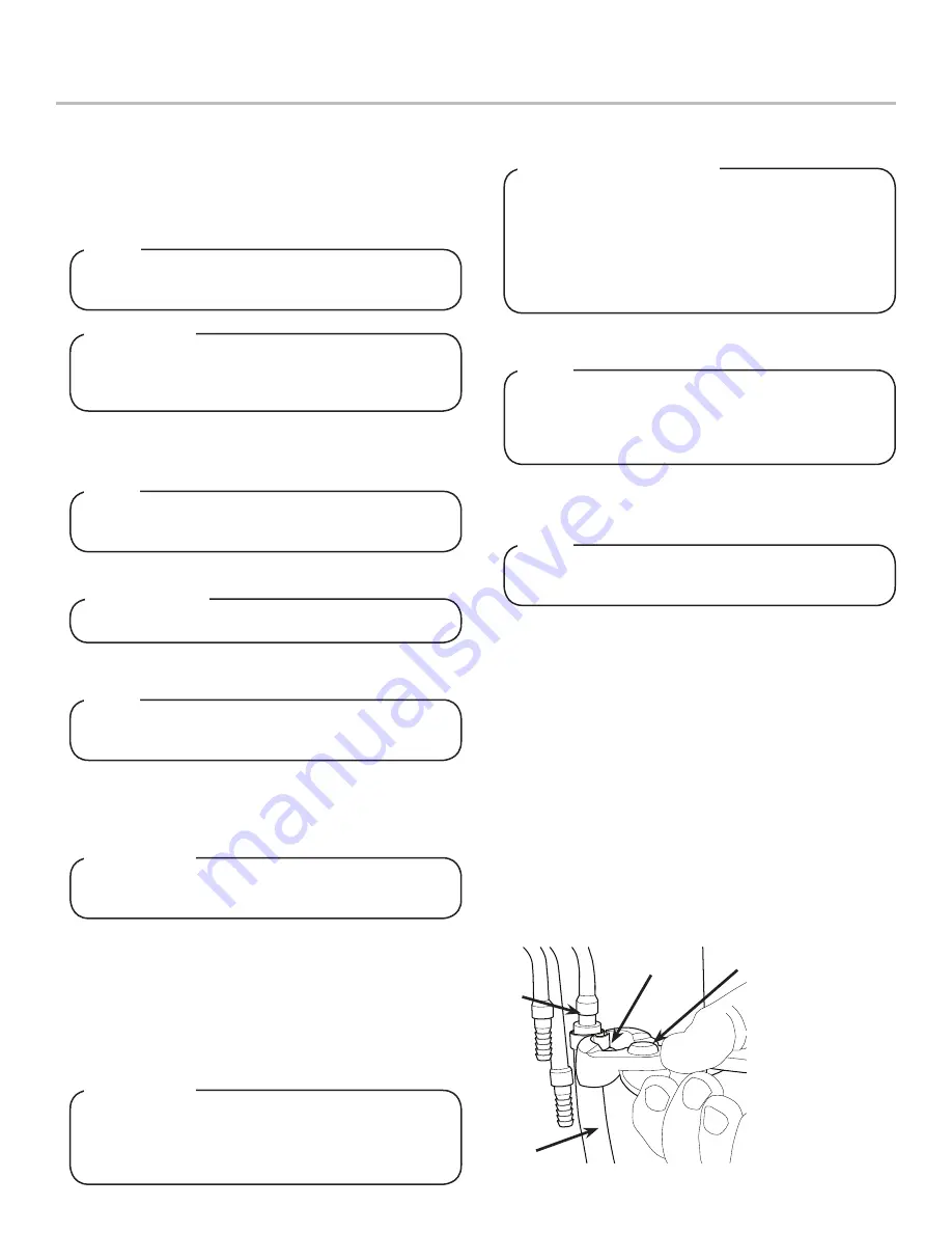
7. Route appropriate tubing from the syrup pump location to the
syrup inlets located behind the splash plate. Connect tubing
to inlets using the oetiker pliers and fittings. Repeat for all
syrup connections.
The installation, and relocation if necessary, must
be carried out by qualified personnel with up-to-date
knowledge and practical experience, in accordance with
current regulations.
NOTE
NSF listed units must be sealed to the counter or use
legs provided.
NOTE
Never energize the machine if there is any trace of
damage. Contact Lancer Customer Service for
assistance.
H
WARNING
Keep ventilation openings, in the appliance enclosure
or in the built-in structure clear of obstruction. Failure
to maintain specified clearance will cause the compres-
sor to overheat and will result in compressor failure.
H
WARNING
A
B
C
A. Oetiker Pliers
B. Fitting
C. Tubing
D. Syrup/Water/CO
2
Inlet
D
When positioning the appliance, ensure the supply
cord is not trapped or damaged.
H
WARNING
2. Select a location for the syrup pumps, CO
2
tank, syrup
containers, and water filter (recommended).
3. Condenser air is drawn in from the front and side vents
located on the bonnet and discharged out the rear of the
bonnet. A minimum of eight (8) inches (203 mm) of clearance
must be maintained over the top of the unit and a minimum
of four (4) inches (101.6 mm) clearance behind the unit to
provide for proper air flow and circulation.


