background image

QUESTIONS?... Contact Customer Service at 1-888-370-6531 M-F 8:00 am- 4:15 pm CST

4


Section 1 - General Specifications & Safety  

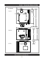
Top View

XT-150/200

Right Side

Left Side

6” diameter

exhaust

18”

4.5”

40.5”

54”

11.5”

28.75”

22.5”

7”

24.25”

5”

26”

48”

Summary of Contents for XT Series

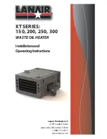
Page 1: ...Lanair ProductsLLC 4109 Capital Circle Janesville Wisconsin 53546 1 888 370 6531 www lanair com XT SERIES 150 200 250 300 WASTE OIL HEATER Installationand OperatingInstructions ...

Page 2: ......

Page 3: ...AL For your safety this manual uses the following definitions and signal words to identify hazards Danger Indicates an imminently hazardous situation which if not avoided will result in death or serious injury This signal word is limited to the most extreme situations Warning Indicates a potentially hazardous situation which if not avoided could result in death or serious injury Caution Indicates ...

Page 4: ...nces The above standards are available from the National Fire Protection Assn Battery March Park Quincey MA 02269 https www nfpa org Read and familiarize yourself with these instructions and associated photos diagrams and illustrations before beginning installation or operation These instructions should be fol lowed closely to achieve the best possible results If you have questions or concerns at ...

Page 5: ...e Sec 5 Installation FuelSupplyTank Piping 20 page Sec 6 Pump Piping FuelSupply 24 page Sec 7 Installation CompressedAir 26 page Sec 8 Diagram ElectricalConnections Wiring 27 page Sec 9 Pump PrimingFuel 31 page Sec 10 Procedure BurnerStart Up 32 page Sec 11 Adjustment Flame 34 page Sec 12 Adjustments MaintenanceSchedule Service 37 page Sec 13 Troubleshooting 45 page Process WarrantyandReturn 50 pa...

Page 6: ......

Page 7: ...or vapors near this heater Fuel storage must be located a minimum of 5 feet from the heater This heater is not designed for use in hazardous atmospheres such as Paint Shops Feed Mills and installations where explosive or flammable conditions are present or could occur DIMENSIONS CABINET XT 150 200 Height 24 25 Width 40 5 Depth 48 Weight 453 LBS XT 250 300 Height 36 Width 45 75 Depth 47 Weight 670 ...

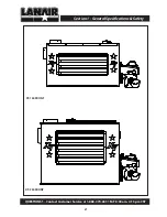
Page 8: ...QUESTIONS Contact Customer Service at 1 888 370 6531 M F 8 00 am 4 15 pm CST 2 Section 1 General Specifications Safety XT 150 FRONT XT 250 FRONT ...

Page 9: ...Visit our website at www lanair com 3 Section 1 General Specifications Safety XT 200 FRONT XT 300 FRONT ...

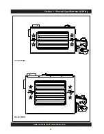
Page 10: ...ntact Customer Service at 1 888 370 6531 M F 8 00 am 4 15 pm CST 4 Section 1 General Specifications Safety Top View XT 150 200 Right Side Left Side 6 diameter exhaust 18 4 5 40 5 54 11 5 28 75 22 5 7 24 25 5 26 48 ...

Page 11: ...Visit our website at www lanair com 5 Section 1 General Specifications Safety 8 diameter exhaust XT 250 300 Right Side Left Side Top View 17 25 5 75 45 75 58 5 11 5 25 24 5 25 36 7 75 38 47 ...

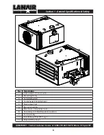
Page 12: ...Description 1 Adjustable Air Flow Louvers 2 Mounting Holes 3 Fan Limit Switch 4 Top Exhaust Port Alternate 5 Flame View Port 6 Burner Assembly 7 Electrical Connections Cover 8 Secondary Air Filter Regulator Location 9 Fan Assembly 10 Side Exhaust Port Primary 11 Rear Ash Box Cover 5 1 2 3 2 2 2 4 6 7 8 9 2 2 2 2 3 9 10 11 ...

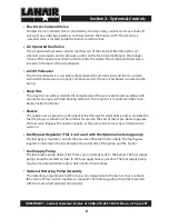
Page 13: ... not press the reset button more than twice If the burner fails to function properly refer to Section 13 Trouble Shooting Fan Limit Control The fan limit control monitors the temperature of the air inside the cabinet When the air reaches a set point usually 120º F it will switch on the heater fan When the temperature in the cabinet drops below set point usually 90º F the fan limit control will tur...

Page 14: ...l pre heater assembly with two resistance type cartridge heating elements The snap disc is mounted on the oil pre heater inside the burner Nozzle The nozzle uses air pressure to help deliver fuel through its small orifice and to atomize the fuel for proper combustion The nozzle is located on the end of the air pre heater opposite the fuel valve Replace the nozzle annually as they are prone to wear...

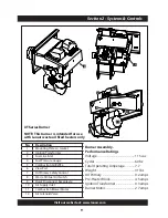
Page 15: ...on 2 Systems Controls XT Series Burner NOTE This burner is intended for use with Lanair waste oil fired heaters only No Description 1 Mounting Plate w Gasket 2 Ignition Transformer 3 Fuel Line Inlet 4 Fuel Pressure Gauge 5 Combustion Air Baffle 6 View Port 7 Oil Primary Safety Control 8 Waste Oil Fuel Oil Switch 9 Quick Disconnect Receptacle 10 Air Supply Inlet 11 Combustion Blower Motor 12 Air So...

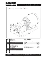
Page 16: ...ator Pump Assembly Performance Ratings Voltage 115 vac Cycles 60 hz Weight 24 lbs Pump Motor 5 amps Max Pumping Distance 30 feet Section 2 Systems Controls No Description 1 Pump Platform 2 Pump Motor 3 Pump Guard 4 Pump 5 Pressure Gauge port 6 Easy Flow Bleed Valve 7 1 4 NPT Inlet 8 1 8 NPT Outlet 9 Pump Motor Coupling ...

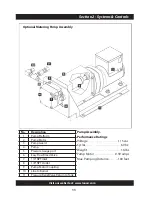
Page 17: ...cles 60 hz Weight 16 lbs Pump Motor 0 59 amps Max Pumping Distance 100 feet Section 2 Systems Controls No Description 1 Pump Platform 2 Pump Motor 3 Pump Guard 4 Pump 5 Pressure Gauge port 6 Easy Flow Bleed Valve 7 1 4 NPT Inlet 8 1 8 NPT Outlet 9 Pump Motor Coupling 10 Line to Burner 11 Pressure Relief Valve Return to Tank ...

Page 18: ...ed in order to eliminate the need to adjust oil flow from a distance 6 Before suspending the heater check the supporting structure and reinforce if necessary to support the weight of the heater system 7 Use 3 8 16 TPI steel threaded rod and locking nuts to suspend the heater from a capable load carrying ceiling structure when not mounting to a Lanair Waste Oil Storage Tank 8 The heater must be sus...

Page 19: ...y cap must be at least 3 ft taller than any object within 10 ft Class A chimney must be used for roof penetration and any exterior chiimney Total chimney length must be at least 10 ft for sufficient draft 10 Primary Strainer 11 Fill Pipe for priming 12 Fuel Pump 13 Fuel Pickup Assembly in tank 14 Tank Drain Compressed air supply electrical shutoff switch tank vent and additional chimney material n...

Page 20: ... Drain Compressed air supply electrical shutoff switch tank vent and additional chimney material not included Installation configurations vary Additional materials will be necessary Contact Lanair for Assistance with special circumstances Heater must be hung at least 8 ft above the floor If the heater is not installed on a tank stand supplied by Lanair a metering pump may be desired in order to el...

Page 21: ... angle elbow con nections where possible Consider chimney cleanout access when installing If your installation fails to acheive proper draft consider lengthening the vertical chimney Contact Lanair for Assistance with special circumstances Keep at least 3 ft to barometric damper from any fan air source return etc Vertical chimney must be a minimum of 10 feet in length to establish proper draft Che...

Page 22: ... Do not reduce or enlarge the vent pipe 5 Minimize or eliminate horizontal runs and angle elbow connections where possible Consider chimney clea nout access when installing If your installation fails to acheive proper draft consider lengthening the vertical chimney Contact Lanair for Assistance with special installation circumstances 6 To prevent the drawing of exhaust gases into the build ing kee...

Page 23: ...ducing a negative 02 W C draft when cold and 05 W C draft when hot 17 If you are unable to attain the proper draft check for exhaust fans in the building To test if there is a problem open an overhead door and see if you now have the proper draft You may have to add one or more sections of Class A chimney to the roof to get the proper draft 18 The heater and chimney must be installed in accordance...

Page 24: ...ort be sure to adhere to height clearance and material requirements If using the top port the installed cap must be removed and placed on the side port using the screws pro vided 10 Slip Connector 14 11 Black Single Wall Pipe 24 12 Black Single Wall Tee 13 Barometric Damper Minimize or eliminate horizontal runs and angle elbow connections where possible Consider chimney cleanout access when instal...

Page 25: ...closer to the damper door will allow the door to open more when a draft is present increasing the draft through the damper and decreas ing the draft through the combustion chamber lowering the manometer reading Adjusting the weight counter clockwise taking the weight farther from the damper door will cause the door to open less when a draft is present decreasing the draft through the damper and in...

Page 26: ...rain should be used for filling the tank Label the fuel tank for the recommended fuels Strain all fuel with a 50 X 50 mesh strainer before putting fuel into the tank When filling the fuel tank with a motorized pump never leave unattended to prevent over filling and or spillage Keep all tank ports except vent s closed when not filling the tank Install equipment in a location that is protected from ...

Page 27: ... as 5W 30 be maintained at 32 F min imum and straight weight oils such as 40W and 50W be maintained at 50 F minimum Tank Mounted Installation Visit our website at www lanair com 5 tected from lift truck and motor NOTE Make sure you have o install and service your heater legs of the tank to the floor as 1 NOTE This method of uggestion only Anchoring ary per individual applications nts Check state a...

Page 28: ...er and allows for adjustments Section 5 Fuel Supply Tank Installation Bypass Regulator Pump Installation 1 2 Soft Copper Tube to Burner 1 2 Return to Tank Pump Assembly Vacuum Gauge P N 8398 Primary Strainer P N 9807 1 2 Pickup Tube Check Valve P N 8662 Suction Line Strainer P N 8748 Drain Valve FRONT VIEW SIDE VIEW Bypass Regulator P N 9570 Bottom of strainer must be 6 from the bottom of the tank...

Page 29: ...ction 5 Fuel Supply Tank Installation Metering Pump Installation 3 8 Soft Copper Tube to Burner 3 8 Soft Copper Tube Return to Tank Metering Pump Assembly Vacuum Gauge P N 8398 Primary Strainer P N 9807 1 2 Pickup Tube Check Valve P N 8662 Suction Line Strainer P N 8748 Drain Valve FRONT VIEW SIDE VIEW Bottom of strainer must be 6 from the bottom of the tank TOP VIEW Tank Gauge Port Fill Port Emer...

Page 30: ...eel pipe or 1 2 outside diameter copper throughout the suction supply line and pick up tube The use of smaller line rubber plastic or hydraulic line is unsafe and will void your warranty 7 Use thread sealing compound on all pipe thread connections Do Not Use Teflon Tape 8 Install the suction line strainer in the suction line Make sure the suction line strainer is 6 off the bottom of the tank The s...

Page 31: ... supply line must gradually rise to the burner It should not be higher than the burner Avoid creating any high points in the line that will trap air bubbles Oil Pressure Bypass Regulator B Port to the oil inlet on the burner assembly Install 1 2 O D min copper tubing Failure to install this line properly will result in damage to your heater and will void your warranty T Port to the oil supply tank...

Page 32: ...t have a filter with a bowl a condensate drain leg must be installed in the air supply line 5 Install a quick disconnect at the air filter regulator on the furnace for service 6 For the ease of installation install a flexible airline 250 I D minimum from the quick disconnect to the primary air regulator 7 The air supply line must be pitched uphill from the primary regulator to the furnace to preve...

Page 33: ...ation A qualified electrician should confirm breaker and wire sizes in accordance with all applicable electrical codes 3 Electrical service connections are made in the electrical junction box on the side of the heater 4 The heater must have a safety equipment ground from the main electrical service strand ed 12 GA minimum 5 The electrical conductors for electrical service to the heater MUST be str...

Page 34: ... Electrical Junction Box Diagram FAN LIMIT HI LOW FAN LIMIT WHITE ROGERS WHITE BLACK RED YELLOW SWITCH RUN PRIME 1 2 3 4 5 6 RUN PRIME 1 2 3 4 5 6 7 8 9 10 11 12 13 1 2 3 4 5 6 7 8 9 10 11 12 13 GEAR MOTOR CAPACTOR WIRE NUT WIRE NUT WIRE NUT WIRE NUT 1 2 3 4 5 6 7 8 9 10 11 12 13 Metering Pump Alternative Wiring ...

Page 35: ...MP Limit In 120V 60 HZ L1 120V 60HZ L2 L2 L2 L2 L2 T1 T2 F1 F2 A A WALL THERMOSTAT YELLOW YELLOW ALARM OPTIONAL COMBUSTION BLOWER TRANSFORMER SNAP DISK MANUAL RESET AIR PRE HEATER OIL PRE HEATER RED BLACK WHITE PRE HEATER SWITCH AIR SOLENOID AIR COMPRESSOR BLACK BLACK BLACK RED BLUE RED ORANGE RED WHITE RED WHITE WHITE WHITE WHITE WHITE WHITE ORANGE ORANGE BLUE BLUE PURPLE WIRE NUT WIRE NUT ...

Page 36: ...ey connector as well as any other hot surfaces Refer to Wiring Diagram for color code etc Wire power to L1 and L2 on the pump Keep the Power off until the heater is ready to be started Room Thermostat Installation 1 All wiring must comply with the National Electrical Code State and Local Ordinances and be wired by a qualified electrician 2 Install the room thermostat in accordance with the directi...

Page 37: ...le the priming switch to the PRIME position 6 When a steady stream of fuel no air bubbles begins to flow close the bleeder screw 7 Toggle the priming switch to the Run position 8 Remove the fuel supply line from the burner and position a container to catch the fuel 9 Toggle the priming switch to the Prime position 10 Observe the end of the fuel supply line that is disconnected from the burner Allo...

Page 38: ...ght ON and wait 5 7 minutes for the pre heater assembly to reach operating temperature Leave the preheater switch OFF if using No 2 fuel oil 8 Set the air baffle position according to your unit XT 150 1 4 open burner air intake grill 25 exposed XT 200 250 1 2 open burner air intake grill 50 exposed XT 300 3 4 open burner air intake grill 75 exposed These are preliminary positions for the air baffl...

Page 39: ...perating NOTE It is VERY IMPORTANT that the barometric damper is set to the required settings to ensure the natural draft of exhaust gases see section 4 13 Depending on the type of fuel used the elevation temperature and oil viscosity the combustion air baffle will need to be adjusted for optimum performance See Section 11 Flame Adjustment 14 When the room thermostat setting is met the burner will...

Page 40: ...and running 3 Check the atomizing air pressure set the air filter regulator on the heater XT 150 200 12 15 PSI XT 250 300 15 18 PSI 4 Ensure that the initial fuel pressure is set according to the table in Section 10 Burner Startup Procedure 5 When using the bypass regulator adjust the thumb screw on the fuel bypass regulator Lock into position The flame should extend no more than 3 4 of the way in...

Page 41: ...g the walls filling the chamber with a smokey flame Correct immediately or chamber may be damaged Problem Too large of a flame dark yellow in color Ash inside the chamber is dark brown to sooty black in color Too much fuel pressure decrease fuel pressure at bypass regulator not applicable for metering pump Not enough combustion air increase opening of burner air baffle Not enough atomizing air pre...

Page 42: ...r flickers Light yellow to white in color REAR OF CHAMBER Flame is under fired Problem Too small a flame flame pulses or sparklers are visible Too much atomizing air pressure decrease atomizing air pressure adjust in 1psi incre ments Too much combustion air pressure close the burner air baffle slightly until flame is CORRECT Not enough fuel pressure when using a bypass regulator increase fuel pres...

Page 43: ... primary air regulator Set to 30 psi Drain water from the air pressure supply line drain leg and primary regulator Inspect the combus tion ash build up and flame NOTE Wear adequate eye face and breath ing protection Check combustion chamber and heat exchanger Clean if necessary Inspect fire brick NOTE Wear protective clothing adequate eye face and breath ing protection Do not breathe dust from the...

Page 44: ...ner needs cleaning 1 Disconnect power to the heater 2 Use a 3 16 hex key to remove the four screws affixing the cannister bowl to the filter head 3 Rinse the filter and lower housing in solvent 4 Air dry the strainer and lower housing 5 Re assemble the strainer ensuring the rubber gaskets and o rings are in place 6 Position the canister bowl to the filter head making sure the o ring is properly se...

Page 45: ...he heater 2 Remove the locking nut and adjusting screw from the bypass regulator assembly 3 Disassemble the bypass regulator and discard the small plug spring large plug washer and diaphragm parts 4 Thoroughly clean and dry remaining parts 5 Re assemble using new small plug spring large plug washer and diaphragm Kit P N 9874 NOTE Pay close attention to the posi tions of the large and small plugs ...

Page 46: ...reheater Nozzle line Assembly Replacement assembly Part 81010396 Diaphragm Assembly Part 9858 Nozzle Assembly Part 9899 Ignitor Assembly Part 3728 Snap Disc Assembly Part 9533 Snap Disc Assembly Part 9533 Oil Cartridge Heater Part 8992 Air Cartridge Heater under diaphragm assembly Part 8992 Reset Switch Reset Switch ...

Page 47: ... of the ignitor and tighten the nut to secure it in place The tips of the ignitor should be 3 8 above the center of the nozzle assembly and should extend ap proximately 1 8 beyond the end of the nozzle The gap between the electrode tips of the ignitor should measure 1 8 at the closest point 6 Use the tool included with the heat er to set the position of the turbula tor then secure it in place Igni...

Page 48: ...ozzle from the air preheater block 3 Disassemble the nozzle as shown and clean thoroughly Reassemble nozzle 4 Carefully remove the quad ring from the block and inspect Replace if nec essary 5 Insert clean new quad ring into the air pre heater block NOTE The quad ring must be properly seated Failure to properly seat the quad ring may result in leakage and improp er burner operation DO NOT INSTALL Q...

Page 49: ...alvanized panel covering the cleanout door remove five 5 10 screws from the top and four 4 10 screws from the bottom of the panel 6 Spray all of the screws with penetrating oil to prevent breakage before removing any of the nuts that secure the combustion chamber access door Let set for five minutes to allow the oil to penetrate 7 Open the clean out door from the heater by removing 8 1 2 hex head ...

Page 50: ...trial type canister vacuum cleaner with a high efficiency filter remove all ash accumulation the chimney connector can also be removed to allow access to the manifold for cleaning 14 Inspect and clean the chimney connector if necessary 15 Replace all gaskets that were removed during the cleaning process Do not reuse gaskets 16 Resecure the access panel and port cover to the heater with the fastene...

Page 51: ...evel A steady stream of oil should flow from the fuel line If the pump will not pump fuel attempt to prime the pump Section 9 If the pump won t prime refer to troubleshooting chart symptom B When using the optional metering pump Pump fuel into a graduated container The flow rate will vary by model XT 150 1 1 gal hr 69 mL min XT 200 1 4 gal hr 88 mL min XT 250 1 8 gal hr 113 mL min XT 300 2 1 gal h...

Page 52: ...QUESTIONS Contact Customer Service at 1 888 370 6531 M F 8 00 am 4 15 pm CST 46 Section 13 Troubleshooting ...

Page 53: ...ator Suction line strainer plugged or dirty Reading gradually decreases Fuel pump output decreasing Fuel viscosity decreasing Orifice in nozzle is wearing Reading gradually increases Fuel pump output increasing Fuel viscosity increasing cold fuel and or gear lube Orifice in nozzle is becoming plugged Reading drops to 0 PSI when the burner is off Dirt between the diaphragm and the seat in the bypas...

Page 54: ...ed or worn nozzle 2 Clean or replace 3 Fuel pressure gauge fluctuat ing pumping system 3 Check pump fittings priming vacuum leak purge air from supply lines 4 Preheater switch is turned off defective or cartridge heater is defective 4 Move switch to ON position test switch and cartridge heater 5 Transformer electrodes not sparking 5 Test transformer look for short circuit contact s and re position...

Page 55: ... fuel pressure 5 Check fuel supply Section 6 and flame adjustment Sec tion 11 6 Improper combustion air baf fle setting combustion blower is defective 6 Adjust flame Section 11 test combustion blower motor replace if necessary 7 Oil primary control flame sensor defective flame sensor and or turbulator improperly adjusted dirty 7 Clean test adjust compo nents replace if necessary 8 Clogged nozzle a...

Page 56: ...ll be fully refunded less restocking fees shipping and handling charges 6 To obtain an authorization number please call our customer service department at 1 888 370 6531 or email us at service lanair com 7 All authorized returns must have the authorization number marked on the outside of the package and returned to the following address Lanair Products LLC Returns Department 4109 Capital Circle Dr...

Page 57: ...f 20 applies on all returned parts Items Not Covered Under Warranty Any portion of the combustion chamber heat exchanger if The unit is not installed per the owners manual The yearly inspection requirements are not current If the heater is used for a purpose for which it is not intended If the heater is not operated in accordance with the printed instructions in the If any alterations or unauthori...

Page 58: ......

Page 59: ......

Page 60: ...ir Products LLC 4109 Capital Circle Janesville Wisconsin 53546 1 888 370 6531 www lanair com 2021 Lanair Products LLC Lanair is a registered trademark of Lanair Products LLC Part 81010423 Rev A July 20 2021 ...

Reviews: