Lampert PUK U5 Operating Manual Download Page 4


Lampert Tools USA 

2020 

  2 


Important! 

"Important!" designates user tips and other especially useful information. This is not a signal word for hazardous or 
dangerous situations. 


2. APPROPRIATE USE (FIELD OF APPLICATION) 


  Outdoor operation is impermissible. Use this device only 

in dry rooms! 

  Welding on all metals and alloys that are suitable for arc 

welding. 


GENERALLY NO LIABILITY IS ACCEPTED FOR THE DURABILITY OF THE WELDING. WE RECOMMEND 
THAT THE WELDING BE CHECKED IN EVERY CASE 


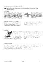
  SM5.1: Observation and microscopic viewing of objects 

through the ocular of the microscope and illumination of 
the working area. 

  The  SM5.1  unit  may  only  be  used  for  welding  if  it  has 

been properly connected to a PUK fine-welding device. 


3. SAFETY INSTRUCTIONS 

 
3.1 GENERAL SAFETY REQUIREMENTS 


PERSONS WHO WEAR ACTIVE IMPLANTS (HEART PACEMAKERS) MUST MAINTAIN A SAFETY 
DISTANCE OF 20 CM BETWEEN THE WELDING CURRENT CABLE / SOURCE OF THE WELDING 
CURRENT AND THE IMPLANT


The opening of the device is only permitted when 
undertaken  by  an  electrician.  Before  opening 
remove the mains cable and ensure that the device 

is de-energised. Discharge any components in the device 
that could hold electrical charge. 

In  case  of  doubt  or  uncertainty,  always  consult  with  a 
specialist.  Our  customer  support  department  is  naturally 
always available to assist you with their professional trained 
personnel, appropriate tooling and equipment. 
Always use the original cables and ensure that workpiece 
clamps are properly attached. 
Both  the  mains  and  welding  currents  can  be  a  source  of 
danger. 
 
The  device must be  isolated  from  the  mains  power  when 
undertaking any repair or maintenance work on the power 
source.  The  power  socket  is  to  be  clearly  blocked  when 
undertaking  any  work  on  the  system  beyond  minor 
manipulations where it is necessary to leave the workplace, 
even for brief periods. 
 
The  highest  and  thus  the  most  dangerous  voltage  in  the 
welding  circuit  is  the  no-load  voltage.  The  highest 
permissible  no-load  voltages  are  recorded  in  the  national 
and international regulations in accordance with the type of 
welding current, construction of the current source and the 
extent of the electrical hazard to the workplace. 
If  it  can  be  assumed  that  risk-free  operation  is  no  longer 
possible, the unit must be put out of operation and secured 
against being unintentionally restarted. 

 
It  can  be  assumed  that  risk-free  operation  is  no  longer 
possible, if  


the equipment shows visible signs of damage, 


malfunctions occur,  


or the equipment is no longer working. 

 
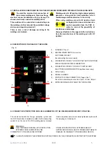
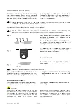
The  PUK  must,  as  standard,  be  operated  with  a  mains 
voltage of 115 V~.  
Yellow-green  wire  =  protective  earth  terminal  (PE).  The 
other wires L1 and N are to be connected to the phase and 
neutral conductors of the power plug.  
The welding device is factory-adjusted to 115 V! 
This means that as a result of the tolerance range +/-10%, 
the  system  can  also  be  operated  at  110  V~.  Devices 
configured to voltages other than 115 V will be designated 
as such by means of a label.  
THE 

DEVICE 

MUST 

ONLY 

BE 

OPENED 

BY 

AUTHORISED SERVICE PERSONNEL!  
IF  THE  DEVICE  HAS  BEEN  CONFIGURED  FOR  A 
CUSTOM  VOLTAGE,  THE  TECHNICAL  DATA  ON  THE 
DEVICE SPECIFICATION PLATE APPLY! MAINS PLUGS 
MUST  CORRESPOND  TO  THE  MAINS  VOLTAGE  AND 
POWER 

CONSUMPTION 

OF 

THE 

WELDING 

EQUIPMENT (see technical data!) 
THE  FUSING  FOR  THE  MAINS  SUPPLY  MUST  BE 
MATCHED  TO  THE  POWER  CONSUMPTION  OF  THE 
WELDING EQUIPMENT! 
ONLY USE THE SUPPLIED MAINS CABLE!  


Summary of Contents for PUK U5

Page 1: ...Operating manual PUKU5 ...

Page 2: ...THE MANUFACTURER ACCEPTS NO LIABILITY FOR DAMAGES CAUSED THROUGH INAPPROPRIATE USE AND IMPROPER OPERATION THE GENERAL SAFETY REQUIREMENTS AND PERSONAL BODY PROTECTION CHAPTERS MUST BE READ BEFORE COMMISSIONING Please keep these operating instructions safe The equipment produced by Lampert Werktechnik GmbH fulfils the conformity requirements of the CE mark and is constructed in accordance with the ...

Page 3: ... 13 6 5 Loading saved programs Pg 13 6 6 Tack welding mode Pg 14 6 7 Micro Pg 14 6 8 Resistance welding mode Pg 14 7 WELDING INSTRUCTIONS 7 1 Introduction to welding Pg 14 7 2 Speed mode only PUK U5 Pg 15 7 3 Welding with the foot switch Pg 15 optional accessory 7 3 1 Fixation welding Pg 15 7 3 2 Resistance welding Pg 16 7 4 Basics and tips Pg 16 7 5 Sharpening the electrodes Pg 16 8 CARE OF THE S...

Page 4: ...en undertaking any repair or maintenance work on the power source The power socket is to be clearly blocked when undertaking any work on the system beyond minor manipulations where it is necessary to leave the workplace even for brief periods The highest and thus the most dangerous voltage in the welding circuit is the no load voltage The highest permissible no load voltages are recorded in the na...

Page 5: ...ly prevented Persons who are nearby to the electric arc and assistants must also be informed of the dangers and equipped with the appropriate protection if necessary set up protective partition walls EYE PROTECTION WHEN OPERATING THE LED ILLUMINATION Never look into the LED lamp or its reflections without eye protection use protective shield or safety glasses with suitable protective glass SMOKES ...

Page 6: ... be covered The device is to be placed on a non combustible surface The device should be set up on a base that is solid level and insulated ideally on a suitable workbench Fasten the two hand supports for the microscope with 2 Allen screws using the supplied Allen key by inserting the screws into the designated holes from underneath the microscope baseplate and into the hand supports ...

Page 7: ...tion 4 3 DESCRIPTION OF THE REAR OF THE DEVICE Fig 2 1 FUSEBOX Fuse 2 MASTER MAINS SWITCH as well as AC POWER SOCKET for connecting the mains cable 3 CONNECTION SOCKET FOR EYE PROTECTION SYSTEM AND LED MICROSCOPE ILLUMINATION 4 CONNECTION SOCKET FOR FOOT SWITCH AND ELECTRODE GRINDING MOTOR optional accessory 5 TYPE PLATE 6 SERIAL NUMBER 7 PROTECTIVE GAS CONNECTION Argon Gas For 6 0 mm diameter pre...

Page 8: ... 11 and tighten up hand tight do not use a tool to tighten The correct length for the electrode can easily be checked and corrected if necessary by means of the milled marks on the handpiece clamping arm Fig 4 Now replace the nozzle The electrode must protrude approx 4 6 mm out of the nozzle Fig 5 ONLY USE THORIUM OXIDE FREE ORIGINAL ELECTRODES Subsequently insert the connector of the handpiece as...

Page 9: ...erocular distance should be individually set for each user FOCUSING Mount the welding handpiece with clamped electrode into the supporting arm Rotate the focusing knob 20 to a medium focus range Adjust the mounting height of the microscope head Hold the microscope head 19 with one hand without touching one of the lenses and use the other hand to release the screw on the head bracket The head can n...

Page 10: ... TIME It jumps back to power automatically after 1 second Turning the controller to the left or the right changes the selected parameter Pressing the controller for a longer time 1 second switches to the next user level see chapter 5 2 TOUCHSCREEN 29 27 Select the material or welding program depending on the user level by sliding to the left or right within the selected user level Press and hold f...

Page 11: ... gas valve lighting At the start level and in Custom Programs sliding in the header bar on the display scrolls between the different preset materials or stored programs depending on the selected user level Beginners using the PUK system are advised to remain within the start level PRESSING THE SELECTED MATERIAL 27 IN THE TOP OF THE DISPLAY FOR 2 SEC CAUSES THE PROGRAMMING MENU TO BE LAUNCHED h Sel...

Page 12: ...he button enables the brightness of the LED lamp on the welding microscope to be adjusted in 3 steps or to be switched off Program memory You can activate or deactivate the saving and calling functions for programs that you created yourself here If this menu is activated it appears as an additional user level The user levels can be toggled by pressing the rotary controller for 1 second Expert Menü...

Page 13: ...ge i e it makes sense to experiment with samples for beginners with the PUK system to find the optimum power level starting at a power of 20 or with very fine welding even lower Power settings between 35 and 50 are considered medium welding powers Power levels above 70 are only practical in the most unusual circumstances There is a danger of inhomogeneous welds and only experienced users should mo...

Page 14: ...ssible DESCRIPTION OF THE WELDING SITUATION WITH ASSOCIATED SYMBOL ON TOUCHSCREEN In the start level the meaning of the following symbols is always the same for each of the preconfigured materials In the start level shows in addition to the welding power and pulse duration for each stored material also the recommended working range in the respective scales of the touchscreen highlighted in colour ...

Page 15: ...auses the info screen to appear for the respective button which contains explanatory information for the button s function Touching the display button again causes the active user screen to be shown once more 6 4 PROGRAMMING SAVING CUSTOM PROGRAMS 1 Pressing the metal name for a longer time 2 seconds calls the programming menu In the first step scroll slide to the left right to select the program ...

Page 16: ...The welding process is released via the foot switch optional accessory which is permanently activated in this welding mode 7 WELDING INSTRUCTIONS NOTE PRIOR TO WELDING ALWAYS CHECK THE FUNCTION OF THE EYE PROTECTION FILTER AS DESCRIBED IN CHAPTER 5 5 FILTER TEST IF THE EYE PROTECTION FILTER SHUTTER FAILS TO SWITCH OVER FROM LIGHT TO DARK THEN IT MUST BE IMMEDIATELY EXCHANGED BY SPECIALIST PERSONNE...

Page 17: ...or operation THE FOOT SWITCH CAN BE ACTIVATED BY PRESSING AND HOLDING IT APPROX 2 SEC AN INFO MESSAGE AND A BLUE SYMBOL APPEAR IN THE DISPLAY Connect a metallic blank section of the workpiece with the contact clamp Now lightly touch the workpiece with the electrode The eye protection system starts to turn periodically from its light to its dark setting If the foot switch is operated in this mode t...

Page 18: ... guarantee BEFORE SWITCHING TO ANOTHER USER LEVEL PLEASE REMOVE THE BLUE CONNECTION CABLE FROM THE PUK U5 7 4 BASICS AND TIPS IMPORTANT Always work with a well sharpened electrode see point 7 4 for information about sharpening the electrodes Ensure extremely good contact between the workpiece and the contact clamp i e make contact between the workpiece and the connection cable terminal at a point ...

Page 19: ... not attempt to disassemble optical components Please contact the local technical customer service department for repairs which are not covered by this manual Remove dust from the lens surface with a special brush prior to cleaning You can obtain suitable accessories in any photography store Cleaning the oculars Do not remove the oculars 17 from the ocular tubes 15 Clean the outer surfaces In doin...

Page 20: ...cation code Optical quality Light scattering Homogeneity Angular dependence Number of the standard 3 11 LWT 1 1 1 3 379 Notified body for CE testing of the LCD Shutter DIN CERTCO Alboinstrasse 56 12103 Berlin 9 5 TYPE PLATE Explanation of pictographs Current Voltage Protection type Hertz Alternating current AC Direct current 1 50 60Hz Mains input 1 phase AC 50 60 Hz Read operating manual No load v...

Page 21: ... to the workpiece 3 No welding current Mains master switch on Fault due to leakage current Switch device off and back on again If fault reoccurs arrange for servicing of device 4 Mains fuse blows or automatic circuit breaker trips Mains insufficiently fused or incorrect automatic circuit breaker Fuse mains properly Mains protection trips during idling Arrange for servicing of device 5 Poor welding...

Page 22: ...NTS A The LED illumination fails to operate Cable not connected Connect the plug to the connecting socket 3 marked with the red and yellow eye protection and illumination symbol on the PUK LED faulty Contact authorized customer service B Eye protection system shutter fails to operate Cable connected incorrectly Connect the plug to the connecting socket 3 marked with the red and yellow eye protecti...

Page 23: ...153 PLEASE NOTE Nozzle 37 clamping nut 38 electrodes and chucks 39 are wearing parts and are not covered by the guarantee 12 DISPOSAL INFORMATION Render discarded devices unusable by removing the mains cable Only for EU countries In accordance with EU directive 2012 19 EU regarding the disposal of used electrical and electronic equipment discarded electrical devices must be separated and collected...

Page 24: ...d to this shipment the separate document Declaration of Conformity Contact Details Lampert Tools USA Inc 67 East Madison 512 Chicago IL 60603 USA Phone 1 866 478 5111 Fax 1312 641 2678 info lampertusa com www lampertusa com SECTION A SAFETY PRECAUTIONS READ BEFORE USING Rev 3 0 ...

Page 25: ...ty Standards Only qualified persons should install operate maintain and repair this unit During operation keep everybody especially children away ELECTRIC SHOCK can kill Touching live electrical parts can cause fatal shocks or severe burns The electrode and work circuit is electrically live whenever the output is on The input power circuit and machine internal circuits are also live when power is ...

Page 26: ... more than one electrode or work cable to any single weld output terminal SIGNIFICANT DC VOLTAGE exists after removal of input power on inverters Turn off inverter disconnect input power and discharge input capacitors according to instructions in Maintenance Section before touching any parts FUMES AND GASES can be hazardous Welding produces fumes and gases Breathing these fumes and gases can be ha...

Page 27: ...red according to AWS F4 1 see Safety Standards Connect work cable to the work as close to the welding area as practical to prevent welding current from traveling long possibly unknown paths and causing electric shock and fire hazards Do not use welder to thaw frozen pipes Remove stick electrode from holder or cut off welding wire at contact tip when not in use Wear oil free protective garments suc...

Page 28: ...a stationary support or cylinder rack to prevent falling or tipping Keep cylinders away from any welding or other electrical circuits Never drape a welding torch over a gas cylinder Never allow a welding electrode to touch any cylinder Never weld on a pressurized cylinder explosion will result Use only correct shielding gas cylinders regulators hoses and fittings designed for the specific applicat...

Page 29: ... adequate capacity to lift and support unit If using lift forks to move unit be sure forks are long enough to extend beyond opposite side of unit OVERUSE can cause OVERHEATING Allow cooling period follow rated duty cycle Reduce current or reduce duty cycle before starting to weld again Do not block or filter airflow to unit STATIC ESD can damage PC boards Put on grounded wrist strap BEFORE handlin...

Page 30: ...Have the installation regularly checked and maintained Keep high frequency source doors and panels tightly shut keep spark gaps at correct setting and use grounding and shielding to minimize the possibility of interference ARC WELDING can cause interference Electromagnetic energy can interfere with sensitive electronic equipment such as computers and computer driven equipment such as robots Be sur...

Page 31: ...w cganet com Code for Safety in Welding and Cutting CSA Standard W117 2 from Canadian Standards Association Standards Sales 178 Rexdale Boulevard Rexdale Ontario Canada M9W 1R3 phone 800 463 6727 or in Toronto 416 747 4044 website www csa in ternational org Practice For Occupational And Educational Eye And Face Protection ANSI Standard Z87 1 from American National Standards Institute 11 West 42nd ...

Page 32: ...ields is a human health hazard However studies are still going forth and evidence continues to be examined Until the final conclusions of the research are reached you may wish to minimize your exposure to electromagnetic fields when welding or cutting To reduce magnetic fields in the workplace use the following procedures 1 Keep cables close together by twisting or taping them 2 Arrange cables to ...

Reviews: