


Lampert Tools USA
2020
15
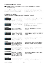
The PUK U5 is equipped with a function to prevent the
electrode becoming welded to the workpiece by
incorrectly pressing too hard. If a welding point has
already been set and is pressed too hard to the
workpiece when it comes into contact again, the welding
point is not triggered; instead, an acoustic signal sounds
periodically to indicate that the electrode is pressing too
hard against the workpiece. The electrode's contact to
the workpiece must be stopped for a short time and the
welding process must be started again.
THE WELDING PROCESS CAN BE HALTED AT ANY TIME BY MEANS OF LIFTING THE ELECTRODE AWAY
FROM THE WORKPIECE.
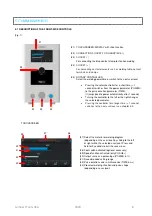
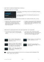
7.2 WELDING WITH THE SPEED MODE (only PUK U5+)
You can press
the according
symbol
on
the display for 1
second to
activate or
deactivate the speed mode. The speed mode can only be
activated on the start level, in the expert menu and on the
"Custom Programs" level. The speed mode enables a
faster welding sequence, e.g. for an increased heat input
into the workpiece. If the user switches to a different user
level, the speed mode must be reactivated if required.
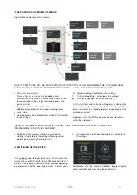
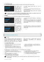
7.3 WELDING WITH FOOT SWITCH
(optional accessory)
With the PUK U5 switched off, connect the foot switch to
the socket (4) marked with the blue foot switch symbol on
the rear of the device. Switch the device on, confirm the
safety prompt by pressing the rotary controller or touching
the screen and wait for the self-test to conclude. The device
is now ready for operation.
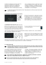
THE FOOT SWITCH CAN BE ACTIVATED BY PRESSING AND HOLDING IT (APPROX. 2 SEC.). AN INFO MESSAGE
AND A BLUE SYMBOL APPEAR IN THE DISPLAY.
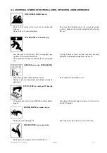
Connect a metallic blank
section of the workpiece
with the contact clamp.
Now
lightly touch the
workpiece
with
the
electrode.
The
eye
protection system starts to turn periodically from its light to
its dark setting. If the foot switch is operated in this mode,
the welding process will begin automatically as described in
chapter 7.1.
PRESSING AND HOLDING THE FOOT SWITCH (APPROX. 2 SEC.) (WITHOUT TOUCHING A WORKPIECE) CAUSES
IT TO BE DEACTIVATED AND THE BLUE SYMBOL ON THE DISPLAY DISAPPEARS.
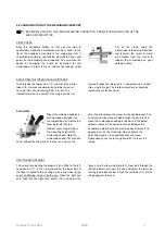
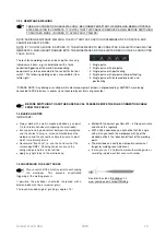
7.3.1 FIXATION WELDING
THE BLUE CONNECTION CABLE MAY ONLY BE CONNECTED AFTER THE MODE HAS BEEN ACTIVATED.
AFTER WELDING IS COMPLETE, IT IS VITAL THAT THIS CABLE IS REMOVED AGAIN, BEFORE SWITCHING
TO ANOTHER MODE, IN ORDER TO AVOID FAULTY WELDS!
Connect both of the workpieces which are to be fixed at
an area of bare metal with a contact clamp, one to the
blue one and the other to the black. When the two parts
are touching, the welding process can be triggered, using
the foot switch. The handpiece is not used during
this process.
The required welding power is determined
by the strength of the connection desired as well as the
workpiece geometry. The welding time setting is of
secondary importance in this mode, and can only be
varied to a very limited extent.
AFTER WELDING HAS BEEN SUCCESSFULLY COMPLETED, AND BEFORE SWITCHING TO ANOTHER
USER LEVEL, PLEASE REMOVE THE BLUE CONNECTION CABLE!
NOTE: DURING FIXATION WELDING, THE FOOT SWITCH IS ALWAYS ACTIVE, AND CANNOT BE
DEACTIVATED! DURING FIXATION WELDING THE GAS PROTECTION IS DEACTIVATED!
Summary of Contents for PUK U5
Page 1: ...Operating manual PUKU5 ...


