


Lake Shore Model 642 Electromagnet Power Supply User’s Manual
Service
7-15
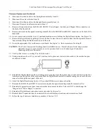
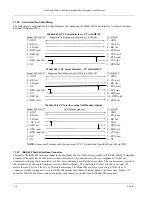
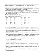
12
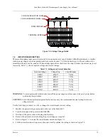
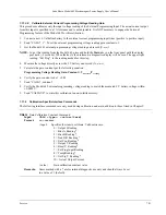
1
24
13
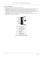
Pin Symbol
Description
1
2
3
4
5
6
7
8
9
10
11
12
13
14
15
16
17
18
19
20
21
22
23
24
DIO 1
DIO 2
DIO 3
DIO 4
EOI
DAV
NRFD
NDAC
IFC
SRQ
ATN
SHIELD
DIO 5
DIO 6
DIO 7
DIO 8
REN
GND 6
GND 7
GND 8
GND 9
GND 10
GND 11
GND
Data Input/Output Line 1
Data Input/Output Line 2
Data Input/Output Line 3
Data Input/Output Line 4
End Or Identify
Data Valid
Not Ready For Data
Not Data Accepted
Interface Clear
Service Request
Attention
Cable Shield
Data Input/Output Line 5
Data Input/Output Line 6
Data Input/Output Line 7
Data Input/Output Line 8
Remote Enable
Ground Wire – Twisted pair with DAV
Ground Wire – Twisted pair with NRFD
Ground Wire – Twisted pair with NDAC
Ground Wire – Twisted pair with IFC
Ground Wire – Twisted pair with SRQ
Ground Wire – Twisted pair with ATN
Logic Ground
Figure 7-12. IEEE-488 Connector Details