Lake Shore Model 642 Electromagnet Power Supply User’s Manual
7-14
Service
7.10.6
Serial Interface Cable Wiring
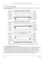
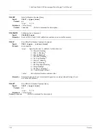
The following are suggested cable wiring diagrams for connecting the Model 642 Serial Interface to various Customer
Personal Computers (PCs).
Model 642 to PC Serial Interface – PC with DE-9P
Model 642 DE-9P
Standard Null-Modem Cable (DE-9S to DE-9S) PC
DE-9P
5 - GND
5 - GND
2 - RD (in)
3 - TD (out)
3 - TD (out)
2 - RD (in)
4 - DTR (out)
6 - DSR (in)
6 - DSR (in)
4 - DTR (out)
1 - NC
7 - RTS (out)
7 - DTR (tied to 4)
8 - CTS (in)
8 - NC
1 - DCD (in)
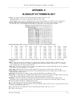
Model 642 to PC Serial Interface – PC with DB-25P
Model 642 DE-9P
Standard Null-Modem Cable (DE-9S to DB-25S) PC
DB-25P
5 - GND
7 - GND
2 - RD (in)
2 - TD (out)
3 - TD (out)
3 - RD (in)
1 - NC
4 - RTS (out)
7 - DTR (tied to 4)
5 - CTS (in)
8 - NC
8 - DCD (in)
6 - DSR (in)
20 - DTR (out)
4 - DTR (out)
6 - DSR (in)
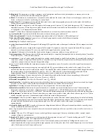
Model 642 to PC Interface using Null Modem Adapter
Model 642 DE-9P
Null Modem Adapter PC
DE-9P
5 - GND
5 - GND
2 - RD (in)
3 - TD (out)
3 - TD (out)
2 - RD (in)
1 – NC (out)
4 - DTR
6 - DSR (in)
1 - DCD (in)
4 - DTR (out)
6 - DSR (in)
7 - DTR (tied to 4)
8 - CTS (in)
8 - NC
7 - RTS (out)
9 - NC
9 - NC
NOTE:
Same as null modem cable design except PC CTS is provided from the Model 642 on DTR.
7.10.7 IEEE-488
Parallel
Interface Connector
Connect to the IEEE-488 Interface connector on the Model 642 rear with cables specified in the IEEE-488-1978 standard
document. The cable has 24 conductors with an outer shield. The connectors are 24-way Amphenol 57 Series (or
equivalent) with piggyback receptacles to allow daisy-chaining in multiple device systems. The connectors are secured in
the receptacles by two captive locking screws with metric threads. The total length of cable allowed in a system is 2
meters for each device on the bus, or 20 meters maximum. The Model 642 can drive a bus of up to 10 devices. A
connector extender is required to use the IEEE-488 Interface and Relay Terminal Block at the same time. Figure 7-12
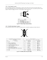
shows the IEEE-488 Interface connector pin and signal names as viewed from the Model 642 rear panel.


