


UNICO 01.07.2019
English / Englisch
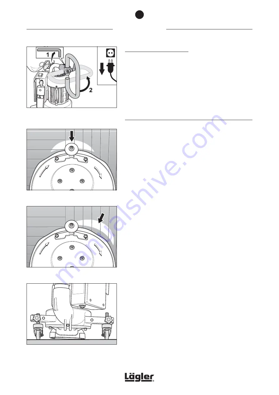
Fig. 23
… the
right-hand
guide roller is further inside
the guide roller arm of the fan housing than the
left-hand guide roller.
Fig. 22
The sanding zone is too far to the
right-hand
side
means that …
Fig. 21
Correctly
adjusted guide rollers. The machine is
sanding in
mid-position
.
Handlebar in horizontal position:
3
Use the enclosed Allen key to undo the screw on the angle
clamping connector of the pipe bend and then rotate the
angle clamping connector by 90° (fig. 20).
4
Use the Allen key to tighten the screw of the angle clamping
connector again.
4.6 ADJUSTING THE GUIDE ROLLERS
The position of the guide rollers has a direct effect on the sanding
results and on the aggressiveness of the machine. For rough
sanding operations, a larger setting angle is selected and a flatter
setting angle for fine-sanding operations.
Normally, the UNICO is supposed to sand the floor precisely at
the front side of the attachment (fig. 21). If this is not the case, the
machine will be sanding on one side (fig. 22 and fig. 24). The height
of one of the guide rollers must then be readjusted (fig. 23 and
fig. 25) because the quality of the sanded section is not the best
and also because this has a negative effect on the suction system.
In case the setting angle of the sanding disc is too large or too
small, both guide rollers must be readjusted. Whenever too much
material is sanded off on too little surface area, the setting angle
is too large and the guide rollers must then be moved further inside
the guide roller arms of the fan housing. Whenever the sanding
capacity is insufficient and the surface being sanded is too large,
you must then move the guide rollers further out of the guide roller
arms of the fan housing.
With a correctly adjusted setting, the sanding zone is located at
the front edge of the attachment (fig. 21).
If the machine is sanding too far to the right-hand side (fig. 22), the
right-hand guide roller is further inside the guide roller arm of the
fan housing than the left-hand guide roller (fig. 23).
Fig. 20
Undo the screw on the angle clamping connector
(1) and rotate the angle clamping connector by
90° (2).
4
COMMISSIONING
22