background image

UNICO  01.02.2013

English / Englisch

SPARE PARTS

52

11

Summary of Contents for UNICO

Page 1: ...English Englisch UNICO EDGE SANDING MACHINE UNICO 00 465 20 002 01 02 2013 00 465 20 002 Operation Maintenance Safety Translation of original operating instructions for the edge sanding machine...

Page 2: ...e sanding machine UNICO Cable support Dust bag MultiClip fastener for dust bag On Off switch Working light Switch box Pipe bend Driving motor Fan housing Machine handle Extension Motor cable Guide rol...

Page 3: ...lication tips 23 5 2 Replacing the abrasives 25 5 3 Removing and emptying the dust bag 28 6 Transport and storage 30 6 1 Machine transport 30 6 2 Machine storage 31 7 Maintenance work and replacement...

Page 4: ...of a quick fastener The dust bag is suspended from the cable rod by means of a textile loop This textile loop keeps the connection cable away from the working zone and is inserted in the holder on th...

Page 5: ...t permitted without the consent of the manufacturer 1 4 PROTECTIVE DEVICES The following parts of the machine are protective devices and must therefore be in perfect condition at all times Velcro seal...

Page 6: ...trical equipment Avoid body contact with grounded parts e g pipes radiators ovens refrigerators The quality of the motor cable and the power cables must match the quality of the original L GLER cable...

Page 7: ...e warning notices of the paint oil and wax manufacturers The dust bag must always be removed from the machine after sanding and emptied into a non combustible con tainer outdoors Cover this container...

Page 8: ...K OF INJURY and RISK OF PROPERTY DAMAGE from uninten tional starting of the machine The power plug must be removed from the socket when the machine is switched off Make sure that ON OFF switch is not...

Page 9: ...for purposes and work that it is not intended for Do not overload the machines It works better and more safely in the power range noted Do not bend too far over the machines Avoid unnatural postures M...

Page 10: ...rly and whether all other conditions which could influence the operation of the machine are in order Damaged safety devices and parts must be properly repaired or replaced by an authorized service sho...

Page 11: ...ission values measuring point at operator s ear 1 5 m above floor Sanding of beechwood parquet using sandpaper grain size 80 77 dB A Measurement uncertainty constant 4 dB A Abrasive commercially avail...

Page 12: ...mentioned below at regular intervals in order to be able to work safely and to achieve the best possible results at all times Renew extension cable after being damaged Renew motor cable after being da...

Page 13: ...o longer required are disposed of properly in accordance with environmental protection regulations The packaging should be used as a transport container in order to ensure safe machine shipment withou...

Page 14: ...make sure that the dust bag is properly positioned without any folds 4 3 INSTALLING THE VELCRO STRIP Depending on the thickness of the abrasive in each case the Velcro sealing strip on the attachment...

Page 15: ...into the clamping piece and tighten the clamping lever firmly Fig 10 4 5 ADJUSTING THE EXTENSION AND THE HANDLEBAR 4 5 1 ADJUSTING THE EXTENSION The extension of the UNICO can be adjusted to suit the...

Page 16: ...out of the clamping piece and remove it upward Fig 15 Put the handlebar aside 5 Undo the clamping lever at the front end of the pipe bend and pull the extension upward out of the bracket Fig 16 Put th...

Page 17: ...d 23 because the quality of the sanded section is not the best and also because this has a negative effect on the suction system In case the setting angle of the sanding disc is too large or too small...

Page 18: ...just the guide rollers proceed as follows 1 Switch off the machine 2 For safety reasons always pull the power supply plug out of the socket to prevent the machine from being started up unintentionally...

Page 19: ...screws with which the wall protecting wheel bracket is fastened to the attachment Fig 27 1 2 4 Move the wall protecting wheel bracket into your desired position Fig 27 3 and then tighten the screws a...

Page 20: ...chine handle is installed on the fan housing as a standard equipment feature 1 Switch off the machine 2 For safety reasons always pull the power supply plug out of the socket to prevent the machine fr...

Page 21: ...ING LIGHT As soon as the connected extension cable has been inserted the working light installed on the UNICO will light up If this is not the case check the power supply For more light from above the...

Page 22: ...sition you will be using one hand to hold the handlebar on the extension Fig 36 or the machine handle on the attachment Fig 37 Now you can start the machine by pressing the rocker switch 4 12 SWITCHIN...

Page 23: ...the calculation of costs NOTE To achieve a very smooth surface in the edge areas of the floors and to carry out the sanding operation for the intermediate lacquer coat you can install a sanding grid...

Page 24: ...to be able to achieve good extraction of the sanding dust The various adjustment possibilities for the extension and the han dlebar are described in Section 4 5 standing working position The height of...

Page 25: ...brasive make sure that the Velcro sealing strip on the attachment is correctly seated You will use various grain sizes of the abrasive depending on the sanding work in each case To replace the abrasiv...

Page 26: ...ut of the socket to prevent the machine from being started up unintentionally 3 Place the UNICO on its side by grabbing the machine by the handlebar on the right hand side and then tilt the machine ov...

Page 27: ...upply plug out of the socket to prevent the machine from being started up unintentionally 3 Place the UNICO on its side by grabbing the machine by the handlebar on the right hand side and then tilt th...

Page 28: ...rioration of the suction performance due to the lack of filtering surface area Do not work with an overfilled dust bag The dust bag must be emptied outdoors When emptying the dust bag wear a respirato...

Page 29: ...from the cable rod Fig 51 2 7 Open the loop of the string on the dust bag Fig 51 3 8 Undo the MultiClip fastener by unscrewing the nut Fig 51 4 9 Pull off the dust bag from the pipe stub carefully Fi...

Page 30: ...E In the event of transport in an automobile or similar machine all parts must be secured against sliding Before transporting the UNICO swivel the working light downward Fig 52 The working light is pr...

Page 31: ...low Maintenance work and replacement of wearing parts 7 MAINTENANCE WORK AND REPLACEMENT OF WEARING PARTS 6 2 MACHINE STORAGE WARNING RISK OF FIRE from spontaneous combustion or the formation of spark...

Page 32: ...ical equipment extension cable plug and couplings 7 2 CLEANING THE V BELT DRIVE UNIT Never use any cleaning products which contain solvents Following the floor restoration work there is the possibilit...

Page 33: ...n carefully Always set the UNICO down on the left hand side Fig 55 This will prevent damage to the floor and the shape of the fan housing also stops any dust falling back out of the dust bag from gett...

Page 34: ...with which the attachment is fastened to the fan housing carefully 7 4 REPLACING THE V BELT Whenever the V belt can no longer be retightened because the fastening screws are up against the slits in th...

Page 35: ...out until this screw disappears on the front side in the threaded hole of the fan housing Fig 63 5 Use the proper Allen key to undo all five screws with which the attachment is installed on the fan h...

Page 36: ...mask at least filter class P2 whenever appropri ate 11 Insert a new V belt Fig 69 Pay attention to the correct installation position of the belt and pull the belt all the way back on the motor side 12...

Page 37: ...ttern of the attachment and the fixture of the sanding disc wheel line up properly insert a screwdriver from above through a hole in the attachment into a hole in the fixture of the sanding disc wheel...

Page 38: ...nstall the new guide rollers and then adjust them as described in Section 4 6 Adjusting the guide rollers 7 6 REPLACING THE WALL PROTECTING WHEEL Use only original L GLER wall protecting wheels part n...

Page 39: ...re you proceed as follows 1 Switch off the machine 2 Always pull the power supply plug out of the socket before performing any work on the electrical equipment 3 Swivel the working light upward Fig 80...

Page 40: ...functional efficiency must also be confirmed Ensure that only original L GLER spare parts are used for mainte nance work You should only allow the customer service work to be conducted by L GLER or a...

Page 41: ...rtable electrical equipment insofar as is used extension and device connection cables with plugs connection cables with plugs movable cables with plugs and fixed connections Inspection interval Every...

Page 42: ...the machine in a warm room to room temperature Undervoltage Check the cable quality and cable length excessively small cable cross sections stranded conduc tor cross sections smaller than 1 5 mm and e...

Page 43: ...being used correct this mistake The machine is vibrating extremely and is working loudly Check the abrasive for signs of damage Check whether the abrasive is fastened in centred position on the sandin...

Page 44: ...ot correct The guide rollers are not correctly adjusted for the respect ive attachment readjust the guide rollers Section 4 6 Adjusting the guide rollers The machine guiding speed is too slow Circular...

Page 45: ...20 230 V 60 CPS 1 1 kW 110 120 V 60 CPS UNICO single phase AC motor Phone 0049 7135 98 90 0 Fax 0049 7135 98 90 98 e mail info laegler com Internet http www laegler com 30 F 220 230 V 130 F 110 120 V...

Page 46: ...UNICO 01 02 2013 English Englisch SPARE PARTS 46 11...

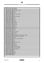
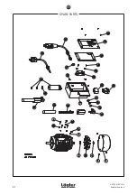
Page 47: ...30 121 Handle 25 9021 1005 000 Washer 26 0912 1005 016 Screw 27 00 000 41 002 Strain relief ring 28 465 08 21 105 Bumper felt 29 000 20 25 065 Cross grip 30 465 60 00 100 Wall protecting roller with b...

Page 48: ...UNICO 01 02 2013 English Englisch SPARE PARTS 48 11...

Page 49: ...105 Fluorescent tube 14 465 63 12 105 Tube 15 0125 1010 000 Washer 16 0439 1010 010 Nut 17 000 65 60 256 Switch 230 V 50 60 CPS 000 65 60 156 Switch 110 120 V 60 50 CPS 000 65 62 160 PVC cap with swit...

Page 50: ...UNICO 01 02 2013 English Englisch SPARE PARTS 50 11...

Page 51: ...30 mm 4 000 70 13 067 V belt 445 01 00 200 Attachment 230 mm complete 5 465 01 01 200 Attachment 350 mm 6 000 70 13 092 V belt 465 01 00 200 Attachment 350 mm complete 7 0965 1005 810 Screw 8 465 01 5...

Page 52: ...UNICO 01 02 2013 English Englisch SPARE PARTS 52 11...

Page 53: ...1 Hexagonal socket screw wrench 4 mm 6 000 93 11 051 Hexagonal socket screw wrench 5 mm 7 000 93 11 061 Hexagonal socket screw wrench 6 mm 10 000 01 10 021 Foldable earmuff type POCKET 11 000 01 10 01...

Page 54: ...UNICO 01 02 2013 English Englisch NOTES 54...

Page 55: ...nature and company stamp Date of test and maintenance work Signature and company stamp Date of test and maintenance work Signature and company stamp Date of test and maintenance work Signature and com...

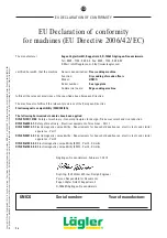
Page 56: ...he following harmonized standards have been applied DIN EN ISO 12100 Safety of machinery General principles for design Risk assessment and risk reduction DIN EN 60204 1 Safety of machinery Electrical...

Reviews: