The edge-detecting timer input modes do require U3 processing resources, as an interrupt is required to handle each edge. Timer
modes 2, 3, 5, 6, 9, 12, and 13 must process every applicable edge (rising
or
falling). Timer modes 4 and 8 must process every
edge (rising
and
falling). To avoid missing counts, keep the total number of processed edges (all timers) less than 30,000 per
second (hardware V1.21). That means that in the case of a single timer, there should be no more than 1 edge per 33 μs. For
multiple timers, all can process an edge simultaneously, but if for instance both timers get an edge at the same time, 66 μs should
be allowed before any further edges are applied. If streaming is occurring at the same time, the maximum edge rate will be less
(7,000 per second), and since each edge requires processing time the sustainable stream rates can also be reduced.
2.10 - SPC (… and SCL/SDA/SCA)
The SPC terminal is used for manually resetting default values or jumping in/out of flash programming mode.
Hardware revision 1.20 and 1.21, had terminals labeled SCL, SDA, and/or SCA. On revision 1.20, these terminals did nothing
except that SCL is used for the SPC functionality described above. On revision 1.21, these terminals were used for asynchronous
functionality, and SCL is used for the SPC functionality described above. Note that these terminals never have anything to do with
I²C.
2.11 - DB15
The DB15 connector brings out 12 additional I/O. It has the potential to be used as an expansion bus, where the 8 EIO are data
lines and the 4 CIO are control lines. The EIO are flexible I/O as described in Section 2.5, so can be used as digital input, digital,
output, analog input, timer, or counter.
In the Windows LabJackUD driver, the EIO are addressed as digital I/O bits 8 through 15, and the CIO are addressed as bits 16-
19.
0-7 FIO0-FIO7
8-15 EIO0-EIO7
16-19 CIO0-CIO3
These 12 channels include an internal series resistor that provides overvoltage/short-circuit protection. These series resistors also
limit the ability of these lines to sink or source current. Refer to the specifications in Appendix A.
All digital I/O on the U3 have 3 possible states: input, output-high, or output-low. Each bit of I/O can be configured individually.
When configured as an input, a bit has a ~100 kO pull-up resistor to 3.3 volts. When configured as output-high, a bit is connected
to the internal 3.3 volt supply (through a series resistor). When configured as output-low, a bit is connected to GND (through a
series resistor).
DB15 Pinouts
1
Vs
9
CIO0
2
CIO1
10
CIO2
3
CIO3
11
GND
4
EIO0
12
EIO1
5
EIO2
13
EIO3
6
EIO4
14
EIO5
7
EIO6
15
EIO7
8
GND
Table 2.11-1. DB15 Connector Pinouts
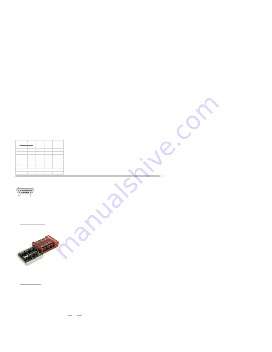
The above image shows standard DB15 pin numbers looking into the female connector on the U3.
2.11.1 - CB15 Terminal Board
The CB15 terminal board connects to the LabJack U3’s DB15 connector. It provides convenient screw terminal access to the 12
digital I/O available on the DB15 connector. The CB15 is designed to connect directly to the LabJack, or can connect via a
standard 15-line 1:1 male-female DB15 cable.
2.11.2 - RB12 Relay Board
The RB12 relay board provides a convenient interface for the U3 to industry standard digital I/O modules, allowing electricians,
engineers, and other qualified individuals, to interface a LabJack with high voltages/currents. The RB12 relay board connects to
the DB15 connector on the LabJack, using the 12 EIO/CIO lines to control up to 12 I/O modules. Output or input types of digital I/O
modules can be used. The RB12 is designed to accept G4 series digital I/O modules from Opto22, and compatible modules from
other manufacturers such as the G5 series from Grayhill. Output modules are available with voltage ratings up to 200 VDC or 280
VAC, and current ratings up to 3.5 amps.
2.12 - U3-OEM
There is an OEM version of the U3 available (-LV and -HV). It is a board only (no enclosure, no screwdriver, no cable), and does
not have most of the through-hole components installed. The picture below shows how the U3-OEM ships by default. Leaving the
through-hole parts off makes the OEM board very flexible. Many applications do not need the through-hole parts, but if needed they
are much easier to install than uninstall.
20


