The Weather Station will automatically detect the tem-
perature probe and will display the temperature probe
data in channel 2.
ADDING TEMPERATURE SENSORS (OPTIONAL)
The WS-9029U is able to receive signals from 2 re-
mote temperature sensors (TX-25U). These extra sen-
sors can be purchased through the same dealer as
this unit
A. SET-UP OF MULTIPLE SENSORS
1. Remove all the batteries from the receiver and
sensor(s) and wait 60 seconds. During these 60
seconds, press any button 20 times to discharge
any excess power.
2. Insert the batteries to the first sensor.
3. Within 2 minutes of powering up the first sensor
(Temperature sensor with probe), insert the batter-
ies to the Weather Station. Once the batteries are
in place, all segments of the LCD will light up briefly.
Following the indoor temperature/humidity and the
time as 12:00 will be displayed, and the signal re-
ception icon will flash. If they are not shown in LCD
after 60 seconds, remove the batteries and wait for
at least 60 seconds before reinserting them.
4. The outdoor temperature from the first sensor
(channel 1) should then be displayed on the
Weather station. If this does not happen after 2
minutes, the batteries will need to be removed from
both units and reset from step 1.
5. If the temperature probe has been used, the out-
door temperature from channel 2 will then be
displayed. Otherwise, the outdoor temperature will
display “—”.
Note: The temperature probe from the first sen-
sor will always occupy “channel 2”. Channel 2 can
only be used for the temperature probe. If you
choose not to use the temperature probe, Channel
2 will display “—”.
6. Insert the batteries to the second sensor as soon
as the outdoor temperature readings from the first
sensor are displayed on the Weather station.
NOTE: You must insert the batteries into the
second sensor within 30 seconds of reception
of the first sensor.
7. The outdoor temperature from the second sensor
and the “channel 3” icon should then be displayed
on the Weather station. If this does not happen af-
ter 2 minute, the batteries will need to be removed
from all the units and reset from step 1.
Note: only the readings from the internal sensor
of the second sensor will be displayed in “channel
3”
IMPORTANT: Transmission problems will arise if the
setting for additional sensors is not followed as de-
scribed above. Should transmission problems
occur, it is necessary to remove the batteries from
all units and start again the set-up from step 1.
B. VIEWING AND OPERATING WITH MULTIPLE
TEMPERATURE SENSOR UNITS
1. To view the temperature of a different remote tem-
perature sensor unit, press and release the SET/
CH button. A shift from one “boxed” number to the
next should be observed in the OUTDOOR LCD.
2. To determine which remote temperature sensor
reading is displayed on the 3 channels, match the
temperature displayed on each channel, with the
corresponding temperature displayed on the LCD
of each remote temperature sensor.
3. To view the Minimum/Maximum temperature: first
select which remote temperature sensor to read
data from (indicated by the “boxed” number), then
press the SET/CH button. Pressing this button once
will display the minimum temperature, and the date
and time the data was recorded. Pressing this but-
ton a second time (while “MIN” is still displayed,
otherwise press the button twice) will display the
same data for the maximum recordings.
4. To reset the Minimum/Maximum readings, press
and hold the MIN/MAX/+ button for 5 seconds, this
will reset all the minimum and maximum data from
all sensors.
MOUNTING
THE REMOTE TEMPERATURE SENSOR
1. Remove the mounting bracket/stand from the tem-
perature sensor.
2. Place the mounting bracket over the desired
location.
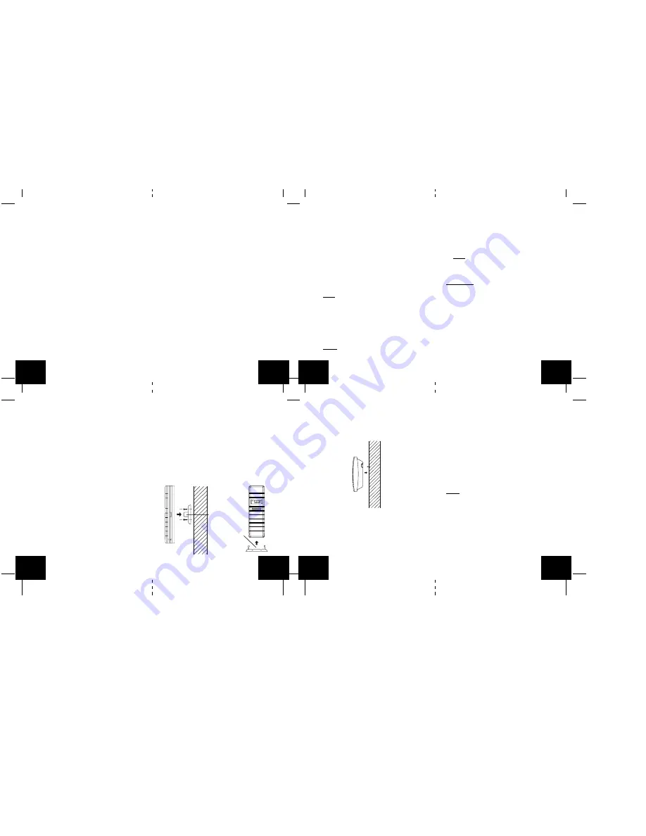
3. The mounting bracket can attach to the sensor in
the middle of the back or on the bottom.
4. Through the 3 screw holes of the bracket, mark the
mounting surface with a pencil.
5. Screw mounting bracket onto the mounting surface.
Ensure that the screws are flush with the bracket.
6. Insert the remote temperature sensor into the
bracket.
THE WIRELESS WEATHER STATION
The wireless weather station can be mounted in 2 ways:
•
with the table stand or,
•
on the wall with the use of a wall hanging screw
(not included).
A. USING THE TABLE STAND
The wireless weather station comes with the table stand
attached. If you wish to use the table-stand all that is
required is to pull out the table stand on the back of the
receiver and place the receiver on a flat surface.
B. WALL MOUNTING
1. Make sure the table stand is flush against the wire-
less weather station.
2. Fix a screw (not included) into the desired wall, leav-
ing approximately 1/4 of an inch (5mm) extended
from the wall.
3. Place the wireless weather station onto the screw
using the hanging hole on the backside.
4. Gently pull the wireless weather station down to
lock the screw into place.
TROUBLESHOOTING
NOTE: For problems not solved, please contact La
Crosse Technology.
Problem: Hour is incorrect (minute and date are correct)
Solution:
Be sure correct time zone and daylight saving time
settings are selected.
Problem: The LCD is faint
Solution:
1. Set the LCD contrast to a higher number
GB
P.14
GB
P.15
GB
P.16
GB
P.17
GB
P.18
GB
P.19
GB
P.20
GB
P.21
Back middle of sensor
inserted into Mounting
Bracket
Bottom of sensor
inserted into
Mounting Bracket
RESETTING THE MIMIMUM AND MAXIMUM
RECORDS
All the minimum and maximum records (minimum and
maximum) will be reset after the MIN/MAX/
+
button is
pressed and held for 5 seconds.
OPTIONAL CHANNEL 2 TEMPERATURE PROBE
When the temperature probe is connected to the re-
mote temperature sensor, the WS-9029U’s channel 1
will display the remote temperature sensor data, and
channel 2 will display the temperature probe data. The
remote temperature sensor data will always be dis-
played on the channel 1 and the temperature probe on
the channel 2.
If the probe on remote temperature sensor is
unplugged, the “probe channel” on WS-9029U LCD will
show “—”, the remote temperature sensor displayed
value will still be shown.
The probe can be connected to the remote tempera-
ture sensor anytime. There is no need to reset the units.