sor (see “A. Temperature sensor” below).
2. Within 2 minutes of powering up the sensor, insert
the batteries to the Weather Station (see “B. Wire-
less Weather station” below). Once the batteries
are in place, all segments of the LCD will light up
briefly. Following the indoor temperature and the
time as 12:00 will be displayed, and the signal re-
ception icon will flash. If they are not shown in LCD
after 60 seconds, remove the batteries and wait for
at least 60 seconds before reinserting them. Once
the indoor data is displayed user may proceed to
the next step.
3. After the batteries are inserted, the Weather Sta-
tion will start receiving data signal from the sensor.
The outdoor temperature should then be displayed
on the Weather Station. If this does not happen af-
ter 2 minutes, the batteries will need to be removed
from both units and reset from step 1.
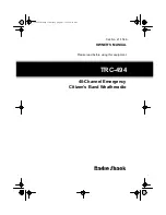
A. TEMPERATURE SENSOR
1. Remove the Battery Cover.
2. Observing the correct polarity, install 2 “AAA” Alka-
line Batteries-make sure they do not spring free,
or start-up problems may occur.
3. Replace the Battery Cover.
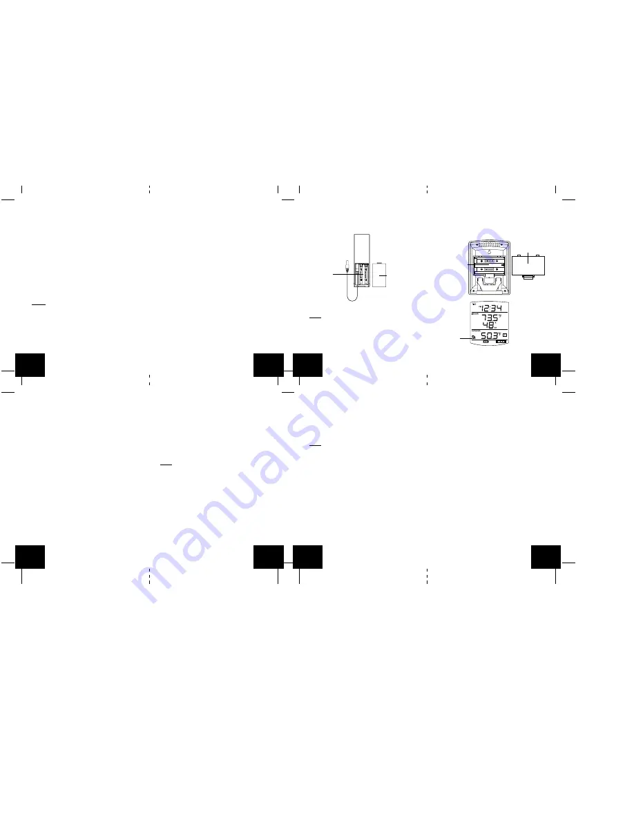
B. WIRELESS WEATHER STATION
Note: After the batteries are installed, DO NOT press
any buttons. This may interfere with the signals, caus-
ing temperatures to register incorrectly.
1. Remove the Battery Cover on the back of the Wire-
less Weather Station.
2. Observing the correct polarity, install 2 “AA” Alka-
line Batteries.
3. Replace Battery Cover.
4. Wait 15 minutes before pressing any buttons.
*
When the signal is successfully received by the
Weather Station, the icon will be switched on. (If
not successful, the icon will not be shown in LCD)
So the user can easily see whether the last recep-
tion was successful (icon on) or not (icon off). On
the other hand, the short blinking of the icon shows
that a reception is being done now.
FUNCTION KEYS
The simple design of this product features 2 keys.
SET/CH:
•
Press and hold for 5 seconds to enter set-up mode.
•
Press and release to toggle between channels.
MIN/MAX/+:
•
Press and release to toggle between minimum,
maximum, and current temperature values.
•
Press and hold 5 seconds to reset all minimum and
maximum recorded values.
•
Press and release to advance hours and minutes.
•
Press and release to toggle between 12 hour time
and 24 hour time.
OPERATIONS
12 OR 24 HOUR TIME SETTING
1. Press and hold the SET/CH button for 5 seconds.
2. “12h” will flash in the Time section of the LCD.
3. Press and release the MIN/MAX/+ button to toggle
between 12 hour time and 24 hour time.
4. Press and release the SET/CH button to confirm
selection and advance to the time setting.
Note: Selecting 12 hour time will automatically select
Fahrenheit (˚F) temperature. Selecting 24 hour time
will automatically select Celsius (˚C) temperature.
TIME SETTING
1. Press and hold the SET button for 5 seconds.
2. “12h” or “24h” will appear flashing in the TIME sec-
tion of the LCD.
3. Press and release the SET/CH button once.
4. The hour will begin flashing.
5. Press and release the MIN/MAX/+ button to ad-
vance the hours.
6. Press and release the SET/CH button once more,
and the minutes will begin to flash.
7. Press and release the MIN/MAX/+ button to ad-
vance the minutes.
8. Press and release the SET/CH button to confirm
selection.
Note: When in the 12-hour format “PM.” will appear
to the left of the hour in the time LCD between the hours
of noon and midnight.
OUTDOOR TEMPERATURE
The temperature received from the remote tempera-
ture sensor is viewed in the OUTDOOR LCD. When
there is more than one remote temperature sensor unit
in operation, a “boxed” number will appear to the right
of the temperature. This indicates which remote tem-
perature sensor unit (1, 2, or 3) is currently displaying
its data in the OUTDOOR LCD. (This feature is ex-
plained in further detail in the section-Adding Remote
Temperature Sensors).
VIEWING MINIMUM AND MAXIMUM TEMPERATURE
RECORDS
The WS-9029U keeps a record of the MINIMUM and
MAXIMUM indoor and outdoor temperatures.
To view minimum and maximum temperatures: press
the MIN/MAX/
+
button once. “MIN” appears in the bot-
tom left of the LCD. The indoor and outdoor tempera-
tures displayed when “MIN” appears are the minimum
recorded values. The minimum records will display for
30 seconds before returning to the normal display mode.
Press the min/max/+ button again (once while “MIN” is
still displayed, twice otherwise). “MAX” appears in the
bottom right of the LCD. The indoor and outdoor tem-
peratures displayed when “MAX” appears are the maxi-
mum recorded values. The maximum records will dis-
play for 30 seconds before returning to the normal dis-
play mode.
While “MAX” is still displayed press the MIN/MAX/
+
button again to return to the current data display. Or
you can wait 30 seconds, during either the minimum or
the maximum readings, and the unit will automatically
return to current data readings.
GB
P.6
GB
P.7
GB
P.8
GB
P.9
GB
P.10
GB
P.11
GB
P.12
GB
P.13
Battery Cover
Remote Temperature Sensor
(TX-25U)
Battery
Compartment
Battery Compartment
Battery Cover
Wireless Weather Station
Sensor Signal
reception icon
*
Weather Station does not display both temperatures
after the 15 minutes, please retry the set up as stated
above. After both indoor and outdoor temperatures
are displayed for 15 minutes you can place your tem-
perature sensor outdoors, and set your time.
The temperature sensor should be placed in a dry,
shaded area (ex: under the eve of a roof). The tem-
perature sensor has a range of 330 feet. Any walls
that the signal will have to pass through will reduce
distance. An outdoor wall or window will have up to 20
feet of resistance and an interior wall will have up to 10
feet of resistance. Your distance plus resistance should
not exceed 330 feet in a straight line.
NOTE: Fog and mist will not harm your temperature
sensor, but direct rain must be avoided.
DETAILED SETUP GUIDE
I.
BATTERY INSTALLATION (When one Tempera-
ture sensor is being used)
1. First, insert the batteries to the Temperature sen-