


23
*
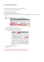
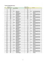
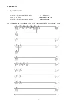
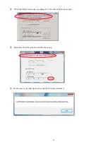
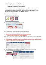
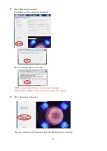
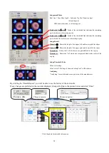
From here, please refer to the “TIP MONITOR SYSTEM INFORMATION CHART” on P.8.
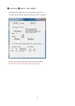
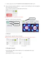
⑤
Here you will need to decide how Indication 1, 2 is going to be shown and the places where the photograph
data is going to appear in the software.
(The green square is the place where photograph data will be shown)
※
Setting of Indication 1, 2 is optional. It can be left blank.
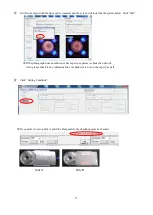
Indication 1, 2 will be shown as the picture below.
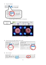
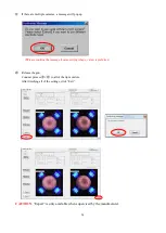
a) Cell Layout
To show the picture, segmentation of the cell is needed.
※
When first set, the cell allocation will be set automatically according to the number of cameras.
3×3
(
up to 8
)
4×4
(
up to 15
)
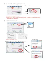
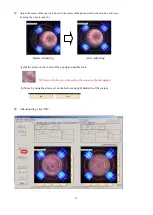
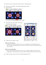
b) Photograph Arrangement
By moving the green squares in the cell, which was set in a), the photograph of the cap tip
can be arranged freely.
Drag the green box to where you want it to appear.
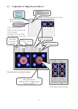
Robot Name
Indication 1
Indication 2
Summary of Contents for TM01-KP-00A
Page 16: ...13...
Page 18: ...15...
Page 36: ...33 When finished click OK Click Save Before Adjusting After Adjusting...
Page 49: ...46 MEMO...
Page 51: ...48...


