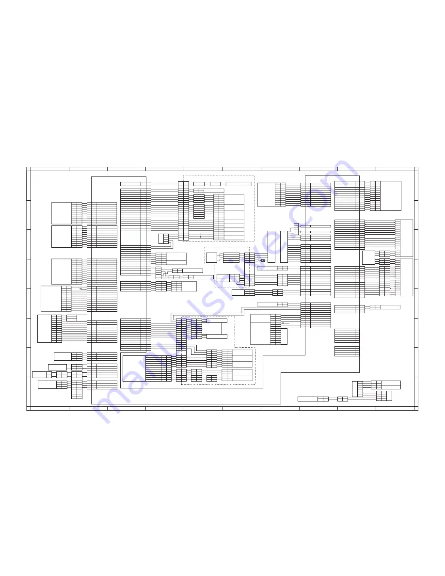
Kyocera KM-6030 Service Manual Download Page 456

2FB/2FC-2.0

2-4-18

Wiring diagram No.4

A

B

C

D

E

F

G

H

I

J

A

B

C

D

E

F

G

H

I

J

1

2

3

4

5

6

7

8

1

2

3

4

5

6

7

8

YC8

YC7

YC1

YC5

YC2

YC14

YC9

YC11

YC3

YC12

YC17

YC15

YC13

YC22

YC6

YC19

YC4

YC20

YC6

YC23

YC10

YC18

3

1

RCSW

12

12

3

10

10

11

11

1
2
3

2

DUPPWB

T COUNT SET SIG

4

1

GND

REM

3

2

2

2

1

1

24V

1

4

2

3

A2

DLP FAN F REM

DLP FAN REM

2

1
2
3

3

1

A3

FIX TH M SIG

A3

A4

A5

A6

B1

B2

B3

B5
B4

B8

R24V

5V

4
5

1

7

DCPS

PWB

LSU-DATA

C1

C3

C2

C2

C3

C1

B7

3

1
2
3

13

3

1

14

1
2

PM

5

A1

3

5

7

B6

2

C3

5

4
5

6

4

3

2

1

2

1

8

9

13
14

2
1

10

1

B13

A6

A5

B1

A7

A2
A1

A8

A8

A1

A13

B8

A7
A6

A6

A10

B11

A10

A11

B4

B8

B6

B6

B5

B7

DUPPWB

YC2

DUPPWB

YC2

DKPWB

YC2

DKPWB

YC2

CSPWB

YC2

DUP SDI

DUP SDO

SGND

A8

A4

8

2

5

2
1

1

17

19

19

6

18

2

2
1

7

1

1

2

1

2

1
2

1

8

9

9

20

2

5

6

7

4

1

1

1

2

20

25

25

3

3
4

29

2

4

A8

3
2

2
1

4

B3
B2

B4

A1

B6

B12

B7

B13

B11

4

2

3

3

3

3

2

8

4

8
9

1

6

6

5

1

2

2
3

3

1

1

A14

A11

A13
A12

A3

4

5

2

3

A6

6

5

A5

3

1

2

1

A4

FS SOL RTN

TRF REM

PGND

R24V
R24V

FEED SHIFT FAN REM

R24V

N.C
N.C

FS SOL PUL

FS SW

16

16

4

12

14

10

8

11

B2

A10

A9
A8
A7

B1

2

14

B5

4

B3

5V

B11

SGND

10
11

10
11
12

1

N.C

3

TRF -CNT

N.C

RxD

SGND

5V

5V

REG SW

6

SGND

3

2

1

2

3

A9

A10

7

7

B7
B8

1

B6

7

3

1
2

SGND

SCK

ERSTN

1

SGND

2

DISPOSL SIG(I)

B3

MAIN MOT ALM
MAIN MOT REM

CONT SET SW

5

B12

B9

TRF INV

TRF +CNT

1

R24V

2

8

11
13

4

12

10

1

7

15

3

4

4

3
2
1

2

GY
RD

GY
RD

2

CL

CLC

DEVS

DEVC

CLM

PCLM

IFFM

DEVFM2
DEVFM1

1

1

9
8
7

2

9

6
7
8

2
1

2

5

12

1

1

2

13

2

R24V

3

5

10
14
18

12

6

A5

DRUM HEAT REM

CL LAMP REM

CL EEPROM SET

SGND

CL EEPROM DATA

REG MOT REM

REG MOT MODE

FEED MOT REM

B3

A3

DUP SEL(O)

N.C

SGND

A5

A9

A4

A1
A2

A12

A3

A2

A1

B1

A3

B2

B9

B5

B4
B5

B7

A11

B10

B6

B8
B7

5

5

6

6

1

1

2

1

VPP

WRSI

3

1

3

5

4

6
7

9

TxD

2

2

3

5

N.C

4

2

FSSOL

FSSW

ESW

FSW1

RSW

3

3

2

RELAY REM

ZEROCROSS REM

1

RIGHT COV SORCE

2

CS SDI

3

24
27

FUSER MOT REM

PGND(N.C)

24

3

27

1

26

29

POTENTIAL SENS SIG

PGND

PGND

PGND

B2

B10

R24V

B1

B11

FUSER MOT ALM

A12

B10

A13

26

SGND

28

31

A13

B1

PGND

B9

B3

B8

B4

A3
A4

A7
A6

A6

A11
A10

A9
A8

15

2

2

B9

REG MOT HLD

B6

REG SW

FEED MOT CLK

1

3

4

6
7

4

4

14

A2

A7
A8

A4

A5

A9

A3

A5

5

2

4

10

12

4

16

4

11
10

3

3

11
10

2

EG SDI

DLP PLS

DLP CONT

4

1

PTC REM

3

EG SDO

EG SDIR

3

EG SBSY

SGND

5

EG IRN

OUTPEN

7

PVSYNC

R5V

SGND

2

PTC ALM

1

15
14
13

EG SGLK

1

PGND

RELAY SOURCE

R24V

SGND

3

S5V

R24V

DLP AC CNT

4

11

11

4

8

9

7

4

2

12

14

3

12

5

11

6

10

13

15

5

8

10

6

7

8
9

10

9

4

G CONT

DLP DC REM

10

9
8

6

DLP AC REM

5

LDON

A2

A1
A2

A10

A1

A11

2

18

6

5

18

16

17

1

1

DUP RDY(I)

DUP SCLK(O)

13

14

16

CL EEPROM CLK

2

7

A9

DUP PAUSE

7

12

16

12

10

1

A4

A1

A6
A7

FEED A SW

EJECT SW

9
8

6
5

1

5

7

3

11

2

3

6
5

11

4

1

4

11
12

12

3

12

8
9

MC ALM
MC REM

10

PGND

13

M HEATER REM

L HEATER REM

15

1

2

5

LSU-LOAD

DF SET

3

3

13

24V

2

14

1

15

2
3

1

OP SDO (DF)

OP SDI (DF)

CS HEATER REM

3

1

2

3

1

2

1
2

1

2

SG (DF)

SG (SF)

3

2

1

5V

3
4
5
6
7
8
9

10
11
12
13
14
15

1-5
1-4
1-3
2-4
2-3
2-2
2-1

2-12
2-11
2-10

2-9

14

SG (SF)

7

7

8

8

SG (SF)

6

6

SG (DF)

9

9

8

3

5

6

4

7

11

13

S HEATER REM

4

WEBSOL

HVPWB

ACPSPWB

DCPSPWB

5

R24V

FIX WEBSOL REM

PFAN REM

1

3

7
6

2

5

1

3

7

6

2

5

1

3

2

4
5

1

9

6

1

6

2

5

WRSO

11

5V

3

1

5V

3

2

6

5

4

4

HEATER LIVE 2

3

3

9

13

2

7

7

5V

7

D HUMID SENS

3

HUMS1

FMDPWB

(B)

(A)

(A)

(C)

(B)

B3

2

5

1

1

1

DUPFM

FSFM

1

1

2

10

1

2

12

4

3

10

8

9

2

9

11

FRCSW

A14

A11
A12

MP TRY SW SIG

A13

CS RDY (I)

3

4

4

4

4

1

1

2

1

2

2

3

3

4

4

1

HUMS2

1

2

2

3

3

1

1

2

2

6

6

1

B8

B5

B7

B2

B3

B6

B3

B7

A4
A3

B4

B10

A1

B9

B11

B1

A9

A7
A6
A5

A8

5

4

4

5

1

1

1

1

2

2

4

3

2

3

3

CFM4

1

1
3

2
1

DRHPWB

2

1

1

2

2

1

1

2

SFM

2

1

1

2

2

1

1

2

DEVDFM

2

1

1

2

LSUFM

A3

4

4
5

1

A2

5

2

3

3
2

1

2

2

3

4

A4

4

2

1

1

1

1

2

A5

B4

3
2

2

4
3

3

3

3

1

2

2

3

1

5

SGND

3

CONT SENS

MP MOT REM

SGND

EJECT SW

1

1

8
9

A12

7

7

B10

B9

B14

A11

12

6

6

B5

5

B12

3

5

4

5

A1

A3

6

THVPWB

5

2

A2

1

9

B4

4

5

B13

B1

7

3
2

2

B14

A4
A5

5

2
1

B8

1
2

A7

B9

B10

1
2

2
1

1

4

3

9

7

D TEMP SENS

TFR MOT ALM

SGND
SGND

TFR MOT REM

15

SGND

MP MOT HLD

15

SGND

FAN STOP

R24V

FEED MOT MODE

FEED MOT HLD

SG (DF)

MP MOT CLK

2

1

DK SDI

DK SDO

SG (DF)
SG (DF)

1
1

COOL FAN3 REM

LSU FAN REM

28

C6

PTS

(C)

CFM3

FH-L

FH-M

FTS

FH-S

FTH-M

FTH-S

SBESW

C4

OP SCLK (DF)

DF RDY

9

DF SEL

SI SEL

SI RDY

SG (DF)

12

6
7
8

10

FEED B SW

MP SOL PULL

2

4

2

2

1
2

1

3

2

4

1

5

4

5

3

DK RDY(I)

31

32

32

30

30

5

DK SCLK(O)

MP SOL RTN

PGND

DK SEL(O)

PLG CLK

B10

B4

B6

B9

B4
B5

B8

B6

B9

B5

B6

B7

B7

B8

B8

B1

3

10

2

9

4

14

10

11

1

13

B10
B11

B3
B2

B5

9

8

7

6

B3
B2

B4

5

9

A12

A11

A3

B2

A8

A5

B11

A9

A10

A4

A9

A5

A7

A7

A4

3

1

1

3

3

PLG READY

PLG REM

A6

A8

A10

4

MP SET SW SIG
MP PSD SW SIG

A9

A3
A2

5

CS PAUSE

B12

B1

2
3

B13

11

3

4

8

4

3

9

12

B11

B3

12

B12

B10
B11

B13

B7

B9

B5

B13

B1

B12

B2

6

2

B4

7

6

4

8

6

WTS

11

PGND

1

8

2

CS SDO

4

3

3

4

11

2

1

4

10

8

2

2

GND

24V

RIGHT COV SIG

MP DIG1

K.CARD REM

SET SIG

FRONT COV SORCE

1

1

5

10

9

9

SGND

5V

PGND
PGND
PGND

1

6

4

7

11

3

6

4

5

1

2

2

5

MP DIG2

CS SCLK (O)

3

1

5

HUMID SENS SIG

TEMP SENS SIG

3

5

6

3

MP DIG0

5V

8

A6

A2

OP SDO (SF)

SG (SF)

OP SCLK (SF)

SGND

PGND

SGND

STOP (SF)

SGND

5

6

6

SG (SF)

SGND

FIX TH S SIG

SB EJ SW SIG

CONVEY U SET SIG

8

7

7

A10

A2

REG MOT CLK

B11

A11

A10

B2

B10

5
6
7

10

11

22

22

10

11

21

12

12

23

23

24

24

21

5V

15

23

9

15

DLP EEPROM DATA

13

DLP EEPROM CLK

9

SGND

13

22

19

3

23

22

3

19

1

11

17

CL MOT MC FWD
CL MOT MC REV

11

17

DLP EEPROM SET

5V

20

6

PGND

CL MOT PTC REV

CL MOT PTC FWD

20

8

6

1

4
2

4
2

8

IMAGE FAN REM

21

DLP SENS SIG

DLP FAN R REM

SGND

21

13

8

14

9

10
11
12

2

SG (SF)

SG (SF)

1

1

SG (SF)

2

2

3

3

4

4

5

5

A5

A6

A4

12

4

11

5

10

6

9

7

8

8

7

A2
A1

B8
B7

10

B6

10

B5

9

6

11

4

12

3

10

5

11

B4
B3
B2
B1

SF SEL

13

2

14

14

1

14

15

OP SDI (SF)

11

SF RDY

12

12

13

13

N.C.

15

8

1

7

2

COOL FAN1 REM

COOL FAN4 REM

MP MOT CWB

MP MOT MODE

A13

A11

14

10

CS SEL (O)

2

2

1

3

3

1

6

5

2

7

14

LSU -CLK

4

4

3

3

FEED A SW

4

6

1

2

PGND

FRONT COV SIG

HEATER LIVE 1

1

2
1

1

3

2

4

5

4

6

4

3

C2

C1

2

1

3

2

1

3

WE

WE

WE

RD
BK

BK

BK
BK

BK
BK

EPWB

8

8

9

9

14
15

8

11

1

1

CFM1
CFM2

1
2

2

2

1
2

4

1

1
2

5

3
2

3
4
5

9

10

13

MPWB

YC1

Key counter

Optional

finisher

Optional

side 

feeder

Total counter

Paper conveying unit

Feedshift unit

Fuser unit

Image formation unit

Summary of Contents for KM-6030

Page 1: ...SERVICE MANUAL Published in March 2006 842FB114 Rev 4 KM 6030 KM 8030...

Page 2: ...sion if battery is incorrectly replaced Replace only with the same or equivalent type recommended by the manufacturer Dispose of used batteries according to the manufacturer s instructions CAUTION Dou...

Page 3: ...Revision history Revision Date Replaced pages Remarks 2 24 June 2005 Overall revised 3 2 December 2005 Overall revised 4 20 March 2006 Overall revised...

Page 4: ...This page is intentionally left blank...

Page 5: ...sonnel to ensure the safety of their customers their machines as well as themselves during maintenance activities Service personnel are advised to read this booklet carefully to familiarize themselves...

Page 6: ...this symbol CAUTION Bodily injury or damage to property may result from insufficient attention to or incorrect compliance with warning messages using this symbol Symbols The triangle symbol indicates...

Page 7: ...or dusty place This may cause fire or electric shock Do not install the copier near a radiator heater other heat source or near flammable material This may cause fire Allow sufficient space around the...

Page 8: ...carefully Always check that the copier is correctly connected to an outlet with a ground connection Check that the power cable covering is free of damage Check that the power plug is dust free If it i...

Page 9: ...trapped wire and missing screws Check that all the caution labels that should be present on the machine according to the instruction handbook are clean and not peeling Replace with new ones if necess...

Page 10: ......

Page 11: ...edure 1 3 1 1 3 2 Setting initial copy modes 1 3 12 1 3 3 Installing the key counter option 1 3 13 1 3 4 Installing the document finisher option 1 3 15 1 3 5 Installing the side feeder option 1 3 24 1...

Page 12: ...riodically 1 5 56 1 5 4 Electric problems 1 5 57 Copier 1 The machine does not operate when the main power switch is turned on 1 5 57 2 The developing motor does not operate C2100 1 5 57 3 The drive m...

Page 13: ...to be loaded is shown when paper is present in cassette 3 1 5 67 59 The message requesting paper to be loaded is shown when paper is present in cassette 4 1 5 68 60 The message requesting paper to be...

Page 14: ...taching the scanner wires 1 6 37 2 2 Fitting the scanner wires 1 6 39 3 Detaching the laser scanner unit 1 6 42 4 Detaching and refitting the ISU reference 1 6 46 5 Adjusting the longitudinal squarene...

Page 15: ...lters 1 6 97 4 Detaching and refitting the image formation fan filter 1 6 98 5 Detaching and refitting the front cover filters 1 6 99 6 Detaching and refitting the ozone filters 1 6 100 1 7 Requiremen...

Page 16: ...0 2 3 10 Operation PWB 2 3 45 2 3 11 DP main PWB 2 3 49 2 4 Appendixes Chart of image adjustment procedures 2 4 1 Image quality 2 4 4 Maintenance parts list 2 4 5 Periodic maintenance procedures 2 4 7...

Page 17: ...1 2 x 11 54 sheets min A3 11 x 17 40 sheets min B4 257 x 364 mm 8 1 2 x 14 50 sheets min B5 80 sheets min B5R 58 sheets min When the document processor is used at 100 magnification A4 11 x 8 1 2 80 sh...

Page 18: ...x 783 D mm 58 1 4 W x 30 13 16 D Functions Selecting image quality Adjusting exposure Auto zoom Manual zoom Preset zoom XY zoom Duplex mode Split mode Sort mode Auto paper selection Offset mode Combin...

Page 19: ...lever 3 Document processor DP 4 Cassette 1 5 Cassette 2 6 Cassette 3 7 Cassette 4 8 MP tray 9 Paper width guides 10 MP tray extension 11 Right cover 12 Handles 13 Main power switch 14 Main power switc...

Page 20: ...ded Indicator 26 Document processor top cover 27 Ejection guide 28 Document processor angle adjustment lever 29 Original eject table 30 Toner container 31 Toner container release lever 32 Paper convey...

Page 21: ...5 Document management key indicator 6 Print management key indicator 7 Repeat copy key indicator 8 Job build key indicator 9 Auto selection key indicator 10 System menu counter key 11 Job accounting...

Page 22: ...Paper and original path 1 Paper feed section 2 Main charging section 3 Optical section 4 Drum section 5 Developing section 6 Transfer section 7 Cleaning section 8 PTC section 9 Fuser section 10 Feeds...

Page 23: ...e system 1 Drive system 1 Optical section Figure 1 1 5 1 Scanner motor 2 Belt scanner 3 Drum pulley 4 Gear Z36 5 Gear Z18 39 6 Pulley scanner 7 Front Rear wire scanner 8 Pulley moving idle 9 Pulley sc...

Page 24: ...Figure 1 1 6 1 Paper feed motor 3 2 Gear cassette feed 3 Upper gear paper feed 4 Joint drive 5 Gear 16 idle 6 Pulley leading feed 7 Paper feed motor 4 8 Gear cassette feed 9 Upper gear paper feed 10...

Page 25: ...6 Belt deck feed 7 Pulley deck 8 Pulley deck 9 Joint drive 10 Gear feed 11 Upper gear paper feed 12 Gear 16 idle 13 Pulley Leading feed 14 Paper feed motor 2 15 Joint drive 16 Upper gear paper feed 1...

Page 26: ...eed motor 2 Belt vertical feed 3 Pulley 26 vertical feed 4 Gear 32 vertical feed 5 Gear 38 vertical feed 6 Gear 38 vertical feed 7 Gear 38 vertical feed 8 Pulley 32 vertical feed 9 Gear 38 vertical fe...

Page 27: ...2FB 2FC 1 1 11 6 Drive system 6 MP tray paper feed Figure 1 1 10 1 MP feed motor 2 Gear 54 MP tray 3 Gear 54 MP tray 4 Gear 44 MP tray...

Page 28: ...istration motor 2 Gear 47 feed 3 Gear 21 feed 4 Gear Z18H feed 5 Gear Z18H Z18S feed 6 Gear 16 registration 7 Feed motor 8 Gear 43 feed 9 Gear 25 feed A 10 Gear 16 registration 11 Pulley 26 one way fe...

Page 29: ...ve 7 Pulley 22 CL 8 Coupling CL drive 9 Developing motor 10 Gear 44 11 Gear 40 DLP 12 Gear 25 DLP 13 Gear 70 DLP 14 Coupling DLP drive 15 Gear 64 DLP 16 Gear 30 50 joint 17 Gear 30 50 joint 18 Gear 40...

Page 30: ...5 7 Fuser motor 8 Gear 88 fuser 9 Gear 40 fixing 10 Gear 19 fixing 11 Coupling fixing joint 12 Gear 133 duplex 13 Gear 71 duplex 14 Gear 29 duplex 15 Gear 19 33 eject 16 Pulley 20 17 Pulley 24 eject 1...

Page 31: ...feed motor 6 Gear DU 17 7 Pulley 24 24 DU conveying 8 Pulley DU tension 9 Belt rear feed 10 Gear 37 24 DU conveying 11 Gear 27 24 one way L 12 Pulley 30 DU 13 Pulley 30 DU 14 Belt front drive 1 Gear 3...

Page 32: ...2FB 2FC 1 1 16 10 Drive system 10 Toner motor drive train Figure 1 1 17 1 Toner motor 2 Gear Z70 Z16S 3 Gear Z56S Z20S 4 Gear 38 5 Gear joint CONT 6 Coupling container...

Page 33: ...3 Gear 33 14 Gear 20 15 Joint PF drive 16 DP lift motor 17 Gear 69 joint 18 Gear 20 65 idle 19 Gear 20 joint 20 Gear 20 65 idle 21 Gear lift 55 22 Gear CIS roller 20 23 Gear CIS idle 21 24 Gear CIS id...

Page 34: ...0 A 220 240 V AC 9 5 A 4 Power source frequency 50 Hz 2 60 Hz 2 5 Installation location Avoid direct sunlight or bright lighting Ensure that the photo conductor will not be exposed to direct sunlight...

Page 35: ...2FB 2FC 1 2 2 Figure 1 2 1 Installation dimensions a d c e f b 30 60 a 680 mm 26 3 4 b 783 mm 30 13 16 c 1190 mm 46 7 8 d 1860 mm 73 3 16 e 1465 mm 57 11 16 f 1530 mm 60 3 16...

Page 36: ...rews Taking out the machine Start Connecting the power cord Adjusting the machine levelness Initial setting for the developing unit Make test copies Installing the guide case Attaching the language la...

Page 37: ...Supports 10 Outer case 11 Upper case 12 Machine cover 13 DP spacer 14 Deck spacers 15 Cassette spacers 16 Sheet 17 DP sheet 18 Rear sheets 19 Hinge joints 20 Plastic bag 21 Operation guide 22 Casette...

Page 38: ...upper left spacer the upper right spacer the outer case and the supports 2 Cut four tapes of the skid each corner 3 Cut each tape which locks the slope and the spacer 4 Rotate slopes as shown in the f...

Page 39: ...over and pull out the handles on machine left and right 6 Lift the machine each left and right one side and then remove the lower left and right spacers 7 Move the machine alongside slopes to slide to...

Page 40: ...tapes two pins for light source unit 1 and pin for light source unit 2 Figure 1 3 5 Remove the tapes pins spacers and sheet DP spacer Tape Tapes Tape DP sheet Tape Tapes Tapes Tapes Tape Tapes Pin for...

Page 41: ...fications Remove the tape of power cord Figure 1 3 6 4 Remove four tapes and two rear sheets Figure 1 3 7 5 Open the DP and then remove three tapes and sheet Figure 1 3 8 Tapes 120 V specifications 23...

Page 42: ...eck spacer of cassette 1 and then remove the guide case Figure 1 3 9 8 Pull out cassette 3 and 4 then remove two cassette spacers and tapes Figure 1 3 10 1 Open the front cover and remove two screws F...

Page 43: ...e the tape from the transfer section 3 Refit the conveying unit Figure 1 3 13 4 Pull out the duplex unit 5 Remove two tapes from the duplex unit 6 Refit the duplex unit Figure 1 3 13 Remove the tapes...

Page 44: ...t ten times to dis tribute the toner evenly 5 Turn the toner container upside down and shake it vertically at least ten times 6 Hold the toner container horizontally and shake it from side to side at...

Page 45: ...d by 180 RESULT Result of the installation 0 During installation 1 Installation is successful 2 Installation is failed If the installation is failed enter 001 using the numeric keys and press the star...

Page 46: ...labels and main power switch label Figure 1 3 18 Figure 1 3 19 1 Attach the guide case to the machine right Figure 1 3 20 Attaching the language label 230 V specifications only MP label DP labels DP...

Page 47: ...y Year inch Day Month Year metric U277 Setting auto application change time 30s U281 Setting stamp mode ON OFF OFF U326 Setting the black line cleaning indication ON U327 Setting the drawer heater ON...

Page 48: ...screws P N B4304100 Two 2 M4 x 10 binding screws P N B8014100 These parts are not used Before installing the key counter press the Power key on the operation panel to off Make sure that the Power lamp...

Page 49: ...rted to the key counter cover retainer on the machine using the screw Figure 1 3 22 7 Insert the key counter into the key counter socket assembly 8 Connect the power cord and turn the main power switc...

Page 50: ...before turning off the main power switch And then unplug the power cable from the wall outlet Turning off the main power switch before pressing the Power key to off may cause damage to the equipped ha...

Page 51: ...op cover affix the sponge in the center of the cover Figure 1 3 25 4 Fix two grounding plate B with the M4 x 8 tap tight S screw to the front back hooks of the finisher Figure 1 3 26 5 Open the front...

Page 52: ...back hole of the finisher and the two short pins align with the holes of the connecting rail 10 Hooking the hooks onto the brackets at the bottom of the machine connect the finisher to the machine Fi...

Page 53: ...e four blue screws locking each of the two separate retainers to the intermediate tray and detach both retainers 14 Pull out the intermediate tray Figure 1 3 32 15 Remove the tape Figure 1 3 33 Link l...

Page 54: ...then remove the four tapes Figure 1 3 35 18 Load two staple cartridges into the staple holders and press down on them until they lock securely into place 19 Close the intermediate tray return it to i...

Page 55: ...all the sub tray by inserting it from above into the hole on the finisher Figure 1 3 37 23 Remove the screw and then remove the sig nal cable cover Figure 1 3 38 24 Connect the signal cable to the con...

Page 56: ...e screw from the lower rear cover of the machine 27 Fit the clamp on non covered part of the sig nal cable to secure the cable to the lower rear cover with the M3 x 10 tap tight S screw 28 Plug the ma...

Page 57: ...front cover 2 Rotate the lower lever by one mark in the direction of the higher numbers There are 5 marks 3 Close the front cover 4 Run paper through the machine and check if it is still curled downw...

Page 58: ...d the copied paper that has been cen terfold stapled with the inside faced down as shown in the illustration Check that the paper is stapled at the center 3 If the staple position is off enter mainte...

Page 59: ...ain power switch And then unplug the power cable from the wall outlet Turning off the main power switch before pressing the Power key to off may cause damage to the equipped hard disk Procedure 1 Cut...

Page 60: ...the machine s right cover 7 Open the right cover Figure 1 3 50 8 Install two M4 x 6 TP screws in the long holes of the fixing plate Align the V groove of the fixing plate with the center of the guide...

Page 61: ...d remove the anchor bracket Figure 1 3 52 10 Set the side feeder on the machine and connect its signal cable to the connector on the back of the machine 11 Attach clamp to the lower rear cover of the...

Page 62: ...outlet and turn on its main power switch 2 Enter maintenance mode and run U034 Adjusting the print start timing 3 Press the interrupt key select the side feeder for the test print mode and then print...

Page 63: ...pped hard disk Procedure Install the printer board 1 Remove three screws and then remove the cover Figure 1 3 56 2 Slide in the printer board along the rails and then secure it with the three screws a...

Page 64: ...Secure the serial interface to the printer board using the two pins 4 Slide in the printer board along the rails and then secure it with the five screws Take care that the power cord does not come in...

Page 65: ...30 Remove the screw of the lower rear cover Fasten all the cables with the clamp and tighten the M3 screw to fix the clamp Make sure that the clamp is facing as shown in the figure Figure 1 3 62 M3 s...

Page 66: ...Remove the two screws and then remove the hole cover 2 Remove the nine screws and then remove the rear middle cover Figure 1 3 63 3 Remove the eight screws and then remove the right sequence cover Fig...

Page 67: ...32 Remove the screw of the lower rear cover Fasten all the cables with the clamp and tighten the M3 screw to fix the clamp Make sure that the clamp is facing as shown in the figure Figure 1 3 66 M3 s...

Page 68: ...ff may cause damage to the equipped hard disk If the machine is using a hard disk already installing the security kit will not erase hard disk data automatically To delete data you need to consult you...

Page 69: ...e board support 5 Return the right sequence cover and rear middle cover to their original positions Figure 1 3 69 6 Plug the machine into a power outlet and turn on its main power switch 7 Confirm tha...

Page 70: ...ic keys Enter 001 using the cursor up down keys or numeric keys and press the start key Enter the maintenance item number using the cursor up down keys or numeric keys The selected maintenance item is...

Page 71: ...fan motors U051 Adjusting the amount of slack in the paper Plain paper Amount of slack for low speed conveying Amount of slack for high speed conveying Amount of slack for duplex low speed feed Amoun...

Page 72: ...1 U099 Adjusting original size detection ORIGINAL LIGHT SOURCE WAIT TIME A4R AREA 72 1 72 1 150 1 240 1 High voltage U100 Adjusting the surface potential 82 1 20 1 0 1 U101 Setting the other high volt...

Page 73: ...he fuser web drive 30 1 U196 Turning the fuser heater on U198 Setting the fuser phase control OFF 120 V ON 220 240 V 1 2 U199 Displaying fuser heater temperature 0 1 Operation panel Optional units U20...

Page 74: ...g the number of sheets to enter stacking mode during sort operation 201 1 2 U331 Switching the paper ejection mode Face up ejection 1 2 U332 Setting the size conversion factor 1 0 1 0 1 2 U335 Setting...

Page 75: ...count 0 1 2 U922 Checking clearing the solenoid count value 0 1 2 U925 Checking clearing the system error counts 0 1 2 U927 Clearing the all copy counts and machine life counts U928 Checking machine...

Page 76: ...er feed loca tion When output is complete the screen for selecting an item is displayed Completion Press the stop clear key at the screen for selecting an item The screen for selecting a maintenance i...

Page 77: ...n the touch panel as shown below To move the cursor press Left or Right in the bottom row 2 Press the start key The telephone number is set and the screen for selecting a maintenance item No is displa...

Page 78: ...n starts Copy operation is simulated without paper under the set conditions When operation is complete the screen for selecting an item is displayed 6 To stop continuous operation press the stop clear...

Page 79: ...ch panel It is displayed in reverse 3 Press the start key All data in the backup memory is initialized and the default setting for the inch spec ifications is registered When initializing is complete...

Page 80: ...tting 1 Select the item to initialize 2 Press EXECUTE on the touch panel It is displayed in reverse 3 Press the start key Backup data is initialized When initializing is complete the machine automatic...

Page 81: ...ption Transfers the backup data of the EEPROM which was transferred with the U026 to flash memory Purpose To use after the main PWB replaced Method 1 Press the start key The screen for executing is di...

Page 82: ...2FB 2FC 2 0 1 4 13 This page is intentionally left blank...

Page 83: ...ned reversing ON high speed PF MOT3 H Paper feed motor 3 PFM3 is turned ON high speed PF MOT4 H Paper feed motor 4 PFM4 is turned ON high speed VF MOT H The vertical feed motor VFDM is turned ON high...

Page 84: ...EJECT SW Exit switch ESW FEED B SW D Feed switch 2 FSW2 LCF SW A Deck conveying switch 1 DKCSW1 LCF SW B Deck conveying switch 2 DKCSW2 FEED C SW Feed switch 3 FSW3 FEED D SW Feed switch 4 FSW4 FEED...

Page 85: ...ges the printing area for copying on folio paper Purpose To prevent cropped images on the trailing edge or left right side of copy paper by setting the actual printing area for folio paper Method Pres...

Page 86: ...ue makes narrower 3 Press the start key The value is set 4 Press the interrupt key 5 Press the start key to output the test pattern 6 Open the front cover 7 Pull the duplex unit out and check the posi...

Page 87: ...or and feed motor are change at the same time 4 Press the start key The value is set Interrupt copy mode While this maintenance item is being executed a VTC pattern shown below is output in interrupt...

Page 88: ...rs periodically sample 2 press the numerical key of Band Cycle to decrease the setting value 4 Press the start key The value is set Supplement Firmware MAIN After 2910BM XXX XX setting possibility Com...

Page 89: ...r OFF The selected item is displayed in reverse Initial setting OFF 2 Press the start key The setting is set Completion To exit this maintenance item without changing the current setting press the sto...

Page 90: ...2FB 2FC 3 1 4 19 This page is intentionally left blank...

Page 91: ...stop clear key at the screen for selecting an item The screen for selecting a maintenance item No is displayed Caution The following settings are also reset to the initial values by performing this m...

Page 92: ...adjustment The screen for selecting a maintenance item No is dis played U064 Adjusting the CCD level Description Adjusts the CCD level Purpose To adjust when density difference due to CCD is generate...

Page 93: ...ST POSITION of the screen for selecting an item 5 Select the Scanning position using the cursor up down keys 6 Press the start key The value is set 7 Set the original the one which density is known in...

Page 94: ...nder the selected conditions 5 To stop operation press the stop clear key Completion Press the stop clear key with the scanning operation stopped The screen for selecting a maintenance item No is disp...

Page 95: ...executing is displayed Setting 1 Change the setting using the cursor up down keys Increasing the setting makes the luminosity higher and decreasing it makes the luminosity lower 2 Press the start key...

Page 96: ...ng auto adjustment DATA XX XX is replaced by an error code is displayed and operation stops Should this happen determine the details of the problem and either repeat the pro cedure from the beginning...

Page 97: ...selecting a maintenance item No is displayed U087 Setting DP reading position modification operation Description Sets the black line inspection at the time of reading the original from the DP Method...

Page 98: ...tting 4 Press the interrupt key The copy mode screen is displayed 5 Press the start key A MIP PG pattern is output Completion Press the stop clear key The screen for selecting a maintenance item No is...

Page 99: ...displayed and operation stops Should this happen determine the details of the problem and either repeat the pro cedure from the beginning or adjust the remaining items manually by running the correspo...

Page 100: ...o return to the screen for selecting an item press the stop clear key Setting Gradient in text mode 1 Select the item to be set The selected item is displayed in reverse 2 Change the setting value usi...

Page 101: ...e screen for selecting an item press the stop clear key Supplement While this maintenance item is being executed copying from an original is available in the interrupt copying mode Completion Press th...

Page 102: ...t Method to set the original size judgment time 1 Adjust the preset value using the or keys A larger value increases the original size judgment time and a smaller value decreases it 2 Press the start...

Page 103: ...lue when poor image quality is caused by dirt in the main charger wire 3 Press the start key The value is set Setting the potential compensation of first copy start 1 Select START ADJ GAIN at the scre...

Page 104: ...EST at the screen for selecting an item 2 Press the start key Drive motor transfer motor and developing motor are turned on and then cleaning lamp and PTC unit is turned on Supplement While this maint...

Page 105: ...ng an item 2 Select 0 OFF or 1 ON The selected item is displayed in reverse Initial setting OFF If ON is selected when the preset number of sheets for charger cleaning operation intervals is exceeded...

Page 106: ...d Press the start key The current counts of the transfer counter is displayed Clearing 1 Press the reset key and press the start key The count is cleared Completion To exit this maintenance item witho...

Page 107: ...til the toner sensor output value reaches the toner feed start level Purpose Used when the toner empty is detected frequently Method 1 Press the start key The screen for executing is displayed 2 Selec...

Page 108: ...he amount of removal toner increases Start Press the start key The screen for selecting an item is displayed Method Toner applying operation mode 1 Select MODE at the screen for selecting an item 2 Ch...

Page 109: ...he screen for selecting a maintenance item No is displayed Maintenance item No Description No Yes Start Does accumulation output number of sheets from previous T7 control exceed 500 Outputting To disc...

Page 110: ...2FB 2FC 3 1 4 37 This page is intentionally left blank...

Page 111: ...the developing drive time for checking a figure which is used as a reference when correcting the toner control Purpose To check the developing drive time after replacing the developing unit Method Pre...

Page 112: ...n fuser temperature sec ondary stabilization fuser temperature aging time after secondary stabilization control temperature adjustment in duplex copying and time from power on to stabi lization of fus...

Page 113: ...user section Purpose To prevent accidents due to an abnormally high fuser temperature Method 1 Press the start key The screen for executing is displayed 2 Press EXECUTE on the touch panel 3 Press the...

Page 114: ...tion Press the stop clear key when fuser heater M S and L are off The screen for selecting the maintenance item No is displayed U198 Setting the fuser phase control Description Sets the use of fuser p...

Page 115: ...e touch panel Purpose To automatically correct the display positions on the touch panel after it is replaced Method 1 Press the start key The screen for executing is displayed and the key displayed at...

Page 116: ...this maintenance item if a key card or key counter is installed Method Press the start key The screen for selecting an item is displayed Setting 1 Select the optional counter to be installed using the...

Page 117: ...the size of paper placed in cassette 1 cassette 2 or optional side feeder is changed Method Press the start key The screen for selecting an item is displayed Setting 1 Press the start key The screen...

Page 118: ...is installed to an optional document finisher Purpose To be set as required according to the user Method Press the start key The screen for selecting an item is displayed Setting 1 Select the item to...

Page 119: ...g an item is displayed Setting 1 Change the setting using the cursor up down keys Initial setting 0 If the preset value is changed to 1 the number of sheets of a stack is limited to 1 500 in modes oth...

Page 120: ...paper conveying belt motor PCBM L is turned on LGR_TEST Front rear upper side registration guide motor SRGM FU RU test operation for 11 x 17 size A3_TEST Front rear upper side registration guide moto...

Page 121: ...e document finisher Method 1 Press the start key The screen for selecting an item is displayed 2 Turn each switch ON manually When a switch is detected to be in the ON position the display for that sw...

Page 122: ..._LM_SW Main tray upper limit detection sensor MTULDS 1000_SW Main tray load 1000 detection sensor MTLDS 10 1500_SW Main tray load 1500 detection sensor MTLDS 15 JTRAY_LLT_SW Multi job tray lower limit...

Page 123: ...e switches on and off manually to check the status If the on status of a switch is detected the corresponding switch is displayed in reverse Completion Press the stop clear key The screen for selectin...

Page 124: ...tional side feeder Method 1 Press the start key The screen for selecting an item is displayed 2 Select the motor to be operated When checking the side feeder lift motor SFLM operation set the paper to...

Page 125: ...position is not proper Setting the punch limit Sets the maximum number of punches possible in order to be informed of the timing for disposing of waste punch Decrease the value when using thick paper...

Page 126: ...tion 1 Select SADDLE STAPLE ADJUST at the screen for selecting an item 2 Select the size to be set 3 Change the setting using the cursor up down keys If the staple position is displaced toward the eje...

Page 127: ...top clear key Maintenance item No Description Copy sample 1 Copy sample 2 Display Description Setting range Default setting Change in value A4R 8 5 x 11 Adjustment of center folding position for A4R 8...

Page 128: ...n for selecting a maintenance item No is displayed Completion To exit this maintenance item without changing the current setting press the stop clear key The screen for selecting a maintenance item No...

Page 129: ...The specified initial settings are provided according to the destinations in the maintenance items below To change the initial settings in those items be sure to run maintenance item U021 after chang...

Page 130: ...ntenance item No is displayed U254 Turning auto start function ON OFF Description Selects if the auto start function is turned on Purpose Normally no change is necessary According to user request chan...

Page 131: ...der request If a paper jam occurs frequently in the optional document finisher when the number of copies is counted at the time of paper ejection copies are provided without copy counts The copy servi...

Page 132: ...ial setting MONTH DATE YEAR for the inch specifications DATE MONTH YEAR for the metric specifications 2 Press the start key The setting is set and the screen for selecting a maintenance item No is dis...

Page 133: ...using the cursor up down keys The setting can be changed by 30 s per step 2 Press the start key The value is set and the screen for selecting a maintenance item No is displayed Completion To exit thi...

Page 134: ...s cleared and the screen for selecting a maintenance item is displayed Completion To exit this maintenance item without changing the current setting press the stop clear key The screen for selecting a...

Page 135: ...Press the start key The setting is set and the screen for selecting a maintenance item No is displayed Completion To exit this maintenance item without changing the current setting press the stop cle...

Page 136: ...OFF Initial setting OFF When setting is turned to ON the setting of U327 is turned as ON and U335 is turned as ON1 or ON2 3 Press the start key The setting is set and the screen for selecting a mainte...

Page 137: ...intenance item without changing the current setting press the stop clear key The screen for selecting a maintenance item No is displayed U344 Setting the low power mode Description Changes the control...

Page 138: ...page 1 6 18 U467 Adjusting the laser output Description Adjusts the laser output power Purpose The setting need not be changed Method Press the start key The screen for adjustment is displayed Settin...

Page 139: ...It is displayed in reverse 3 Press the start key All data in the scanner NIC is initialized Completion To exit this maintenance item without executing initialization press the stop clear key The scre...

Page 140: ...exit this maintenance item without changing the current setting press the stop clear key The screen for selecting a maintenance item No is displayed U508 Setting the LDAP Description Enables or disab...

Page 141: ...d U511 Setting scan To FTP Description Sets whether or not scan to FTP setting is enabled if an optional network scanner is installed This maintenance mode is effective for only 120 V specifications P...

Page 142: ...Purpose To check the paper jam status Also to clear the jam counts after replacing consumable parts Start Press the start key The screen for selecting an item is displayed Method Displays clears the...

Page 143: ...e counts for all service call press the reset key and then press the start key The count is cleared Method Displays the total call for service counts 1 Select TOTAL COUNT in the screen for selecting a...

Page 144: ...screen for selecting a maintenance item No is displayed U906 Resetting partial operation control Description Resets the service call code for partial operation control Purpose To be reset after partia...

Page 145: ...s the total counter value Purpose To check the total counter value Method Press the start key The screen for total count value is displayed Completion Press the stop clear key The screen for selecting...

Page 146: ...count is cleared When clearing all counts the screen for selecting a maintenance item is displayed Completion To exit this maintenance item without changing the count press the stop clear key The scr...

Page 147: ...and press the reset key 2 Press the start key The count is cleared Completion To exit this maintenance item without changing the count press the stop clear key The screen for selecting a maintenance N...

Page 148: ...54 Setting the type of cooling fan Description Sets the new or old type of cooling fan Purpose To change the setting according to the type of the cooling fan Method Press the start key The screen for...

Page 149: ...e screen for selecting a maintenance item No is displayed U985 Displaying the developing unit history Description Indicates the past record of machine number and the developing counter Purpose To chec...

Page 150: ...rt key The screen for selecting an item is displayed The accumulated time of illumination for the exposure lamp is displayed in minutes Clearing 1 Select the item to be cleared 2 Press the reset key 3...

Page 151: ...age accounting the copy count page 1 4 77 Press Copy Default Press Machine Default Start Make copy default settings page 1 4 78 Make machine default settings page 1 4 80 Press Print Report Output the...

Page 152: ...copy count Tracks the total copy counts of all departments and print the total in the form of job accounting reports The total copy count can be reset as necessary 1 Press Management Total The total c...

Page 153: ...Close 8 Press Close 3 Default settings for copying Exposure mode Exposure mode changes the default for how the copier adjust how dark or light copying is made 1 Select Exposure Mode using the cursor u...

Page 154: ...t Adjust auto exposure using the cursor up down keys and press Change 2 Press Lighter or Darker to adjust the exposure Setting range 3 to 3 Adjusting automatic exposure for scanning text doc uments Ad...

Page 155: ...e layout of the additional functions screen 1 Select Customize User Choice Customize Add function using the cursor up down keys and press Change 2 Highlight the menu item on the right side frame using...

Page 156: ...press Change When the size of the original document is cardstock or A6R select Cardstock or A6 When the size of the original document is B4R or Folio select B4 or Folio When the size of the original d...

Page 157: ...disk contents Sets the method for erasing the contents of the hard disk when the copier is equipped with the optional security kit 1 Select Hard Disk Delete Method using the cursor up down keys and pr...

Page 158: ...box name and press End 4 Specify the password to the box 5 Select Password and press Change 6 Enter the password using the numeric keys and press Close The password should be a number up to 8 digits...

Page 159: ...12 Refreshing the drum Refreshing the drum is recommended if images on copies appear blurred or warped or if blank areas appear Load the paper of size 11 x 8 1 2 or A4 or 11 x 17 or A3 in the MP tray...

Page 160: ...in the duplex section draw out the duplex unit When paper is jammed in the DP open the document processor top cover or document processor bottom cover Paper misfeed detection can be reset by opening a...

Page 161: ...ection conditions Figure 1 5 2 FSSW SBESW DUPCSW2 DKCSW1 DKCSW2 TIMSW1 RSW FSW2 FSW4 FSW5 TIMSW3 DUPSBM FDM DPTSW1 DPTSW2 TIMSW2 FSW3 DUPSRM DUPCSW3 DUPCSW1 DUPFSW ORM 1 OCM RM PFM2 PFM3 PFM4 PFM1 DUP...

Page 162: ...ten for the specified time of less then A4 11 x 8 1 2 size 14 No paper feed from side feeder Side feeder feed switch SFFSW does not turn on within 2000 ms of the side feeder paper feed clutch SFPFCL t...

Page 163: ...2500 ms 720 ms for 60 cpm of its turning on Feed switch 5 FSW5 does not turn on within specified time 1590 ms 1166 ms for 80 cpm 2046 ms 1166 ms for 60 cpm of timing switch 3 TIMSW3 turning off Descr...

Page 164: ...urning on 32 Misfeed in registration Feed switch 1 FSW1 does not turn on within specified time 800 ms 586 ms for 80 cpm 1029 ms 586 ms for 60 cpm of feed switch 2 FSW2 turning on Description in is wri...

Page 165: ...m cassette 3 43 Misfeed in fuser section 4 Exit switch ESW does not turn on within specified time 1350 ms for 80 cpm 1736 ms for 60 cpm of its turning on when paper is fed from cassette 4 44 Misfeed i...

Page 166: ...x 8 1 2 size 66 Misfeed in duplex convey ing section 3 Duplex conveying switch 3 DUPCSW3 does not turn on within specified time 750 ms for 80 cpm 1000 ms for 60 cpm of duplex conveying switch 2 DUPCS...

Page 167: ...off within 1500 ms of its turning on When the intermediate tray paper conveying sensor ITPCS does not turn on within 2000 ms of the sub tray paper ejection sensor STPES turning on 85 Paper jam during...

Page 168: ...erfold unit paper entry sensor CUPES turning on 94 Jam in saddle eject sec tion The folded edge detection sensor FEDS is not turned on even if 5000 ms elapse after centerfold operation starts 95 Jam i...

Page 169: ...eed switch 2 actua tor Check visually and replace the upper feed sensor if its actuator is broken Defective feed switch 2 Run maintenance item U031 and turn feed switch 2 on and off manually Replace f...

Page 170: ...replace any deformed pulleys Defective timing switch 3 Run maintenance item U031 and turn timing switch 3 on and off manually Replace timing switch 3 if indication of the correspond ing sensor on the...

Page 171: ...orresponding sensor on the touch panel is not displayed in reverse Defective timing switch 2 Run maintenance item U031 and turn the timing switch 2 on and off manually Replace the timing switch 2 if i...

Page 172: ...on the touch panel is not displayed in reverse The vertical feed roller or deck conveying roller is dirty with paper powder Check and if it is dirty clean it The vertical feed roller or deck conveying...

Page 173: ...ve feed switch 5 Run maintenance item U031 and turn feed switch 5 on and off manually Replace feed switch 5 if indication of the corresponding sensor on the touch panel is not displayed in reverse Def...

Page 174: ...ensor on the touch panel is not displayed in reverse Broken deck conveying switch 2 actuator Check visually and replace deck conveying switch 2 if its actuator is broken Defective deck conveying switc...

Page 175: ...ce the side feeder feed switch if indica tion of the corresponding sensor on the touch panel is not dis played in reverse The feed roller or feed left roller is dirty with paper powder Check and if it...

Page 176: ...off manually Replace feed switch 1 if indication of the corresponding sensor on the touch panel is not displayed in reverse Defective registration switch Run maintenance item U031 and turn the registr...

Page 177: ...n fuser section 5 Jam code 44 Defective exit switch Run maintenance item U031 and turn the exit switch on and off manually Replace the exit switch if indication of the correspond ing sensor on the tou...

Page 178: ...med or worn fix or replace it 32 A paper jam in the duplex section is indi cated during copying jam in duplex inter nal tray Jam code 62 Broken duplex feed switch actuator Check visually and replace t...

Page 179: ...the corresponding sensor on the touch panel is not displayed in reverse Broken duplex conveying switch 1 actuator Check visually and replace duplex conveying switch 1 if its actua tor is broken Defect...

Page 180: ...he status and rem edy if necessary 38 An original jams in the optional DP is indicated during copying jam in the original feed convey ing section 1 Jam code 71 Defective DP timing switch 2 Run mainten...

Page 181: ...ly Replace the paper entry sensor if indication of the corresponding sensor on the touch panel is not displayed in reverse 45 A paper jam in the optional document finisher is indicated during copying...

Page 182: ...eject sensor if indication of the corresponding sensor on the touch panel is not displayed in reverse 50 A paper jam in the optional document finisher is indicated during copying jam in eject section...

Page 183: ...sensor if indication of the corresponding sensor on the touch panel is not displayed in reverse 56 A paper jam in the optional document finisher is indicated during copying jam in saddle tray sec tion...

Page 184: ...2FB 2FC 4 1 5 25 This page is intentionally left blank...

Page 185: ...then on If the error is detected continuously however perform the operation shown in Table 1 5 1 If a system error occurs fre quently a fault may have occurred Check the details of the C call to take...

Page 186: ...ment finisher punch motor problem C8030 Document finisher upper paper conveying belt problem C8040 Document finisher lower paper conveying belt problem C8140 Document finisher main tray problem C8150...

Page 187: ...PWB Replace the main PWB and check for cor rect operation Device damage of EEPROM Contact the Service Administrative Division C0140 Backup memory EEPROM data problem Data damage of EEPROM Contact the...

Page 188: ...rrect operation C0250 Network scanner board communica tion problem The response to the alive command to the network scanner transmitted once to 30 s does not come on the contrary three consecutive tim...

Page 189: ...e PWB and YC2 on the duplex PWB and the continuity across the connec tor terminals Repair or replace if necessary Defective engine PWB Replace the engine PWB Defective duplex PWB Replace the duplex PW...

Page 190: ...t finisher EEPROM error A backup memory error is received in serial communication data from the fin isher Defective optional document finisher Replace the document finisher with another unit and check...

Page 191: ...If none repair or replace the cable Defective deck PWB Replace the deck PWB C1020 Lift motor 2 error When cassette 2 is inserted lift limit switch 2 does not turn on within 33 s of lift motor 2 turnin...

Page 192: ...or continuity across the coil If none replace lift motor 4 Poor contact of lift motor 4 connector terminals Reinsert the connector Also check for conti nuity within the connector cable If none repair...

Page 193: ...tration motor Replace the duplex side registration motor Defective duplex PWB Replace the duplex PWB C2100 Developing motor error LOCK signal remains high for 1 s 1 s after the developing motor has tu...

Page 194: ...tive drive transmission sys tem Check if the rollers and gears rotate smoothly If not grease the bushings and gears Check for broken gears and replace if any Defective cassette PWB or engine PWB Repla...

Page 195: ...rect operation Poor contact in the connector termi nals Check the connection of connector YC2 on the DP main PWB and the continuity across the connector terminals Repair or replace if necessary Defect...

Page 196: ...see page 1 6 42 Defective engine PWB Check if 24 V DC is supplied to YC17 1 on the engine PWB If not replace the engine PWB C4010 Polygon motor steady state problem The polygon motor rotation is not s...

Page 197: ...high voltage Check the main charger unit and replace if necessary see page 1 6 31 Poor contact in connector termi nals Check the connection of connector YC7 on the engine PWB and the continuity across...

Page 198: ...temperature does not increase for 40 s after the fuser heat ers have been turned on for warming up The fuser temperature remains below 50 C 122 F for 10 s continuously after the fuser heaters have bee...

Page 199: ...e replace the fuser heater L M and S see page 1 6 76 Defective engine PWB Replace the engine PWB Defective AC power source PWB Replace the AC power source PWB C6400 Zero cross signal error The engine...

Page 200: ...e PWB and the continuity across the connector terminals Repair or replace if necessary Defective humidity sensor Replace the humidity sensor Defective engine PWB Replace the engine PWB C8010 Document...

Page 201: ...sher main PWB Replace the finisher main PWB and check for correct operation C8040 Document finisher lower paper con veying belt problem During initialization the intermediate tray lower sliding plate...

Page 202: ...nsor and check for correct operation Loose connection of the main tray load detection sen sor connector Reinsert the connector Also check for conti nuity within the connector cable If none remedy or r...

Page 203: ...finisher main PWB Replace the finisher main PWB and check for correct operation C8180 Document finisher rear upper side registration guide problem During initialization the rear upper side registrati...

Page 204: ...front sta pler home position sensor does not turn off within 500 ms Loose connection of the front stapler motor connector Reinsert the connector Also check for conti nuity within the connector cable I...

Page 205: ...the problem occurs after ini tialization when the front cover is opened and closed the problem is in the rear clincher When the rear clincher is operated from the home position the rear clincher home...

Page 206: ...check for conti nuity within the connector cable If none remedy or replace the cable Defective center fold unit main PWB Replace the centerfold unit main PWB and check for correct operation C8320 Doc...

Page 207: ...tor cable If none remedy or replace the cable Malfunction of the DP lift motor Replace the DP lift motor and check for cor rect operation Malfunction of the DP lift upper limit switch Replace the DP l...

Page 208: ...ion of the SHD PWB Reinsert the connector Also check for conti nuity within the connector cable If none remedy or replace the cable Defective SHD PWB Replace the SHD PWB and check for cor rect operati...

Page 209: ...5 51 See page 1 5 52 See page 1 5 52 See page 1 5 52 See page 1 5 53 11 The leading edge of the image is consis tently mis aligned with the original 12 The leading edge of the image is spo radically m...

Page 210: ...lar error between the leading edges of the original and copy image when the DP is used 22 A line appears at the leading or trailing edge 23 A line appears periodically See page 1 5 56 See page 1 5 56...

Page 211: ...s run If not replace the engine PWB C Defective transfer high voltage PWB Replace the transfer unit see page 1 6 61 2 No LSU laser is output A Defective laser scanner unit Replace the laser scanner un...

Page 212: ...ight A The connector terminals of the exposure lamp make poor contact Reinsert the connector Also check for continuity within the connector cable If none remedy or replace the cable B Defective invert...

Page 213: ...ontinuity within the connector cable If none remedy or replace the cable B Poor insertion transfer unit Reinstall the transfer unit C Continuity malfunction inside the transfer belt Check for continui...

Page 214: ...plate 4 Dirty DP separation roller Clean the DP separation roller 5 Foreign matter in the laser scanner unit Replace the laser scanner unit see page 1 6 42 6 Dirty CIS or CIS roller Clean the CIS or...

Page 215: ...in charger wire Clean the wire or if it is extremely dirty replace it see page 1 6 33 2 Defective exposure lamp Check if the exposure lamp light is distributed evenly If not replace the exposure lamp...

Page 216: ...registration see page 1 6 25 2 Misadjusted scanner leading edge regis tration Readjust the scanner leading edge registration see page 1 6 54 3 Registration motor operating incorrectly Check the instal...

Page 217: ...the paper type of machine default is proper see page 1 4 80 3 The paper is not loaded correctly Load the paper correctly 4 Defective fuser section Check the heat roller and press roller 5 Decrease of...

Page 218: ...e scanning unit see page 1 6 46 2 Drum condensation Clean the drum 18 Image center does not align with the original center Causes 1 Misadjusted center line of image printing 2 Misadjusted scanner cent...

Page 219: ...ve measures 1 Misadjusted original scanning start posi tion Readjust the DP leading timing see page 1 6 93 22 A line appears at the leading or trailing edge Causes 1 Misadjusted of the speeds of the m...

Page 220: ...does not operate C2200 1 Poor contact in the drive motor connector termi nals Reinsert the connector Also check for continuity within the con nector cable If none remedy or replace the cable 2 Defect...

Page 221: ...and check if paper feed motor 1 operates If not replace paper feed motor 1 7 Paper feed motor 2 does not operate 1 Poor contact in paper feed motor 2 connector terminals Reinsert the connector Also c...

Page 222: ...ntenance item U030 and check if the MP feed motor operates If not replace the deck PWB 12 The vertical feed motor does not oper ate 1 Poor contact in the verti cal feed motor connector terminals Reins...

Page 223: ...cable If none remedy or replace the cable 2 Broken polygon motor Replace the laser scanner unit see page 1 6 42 18 Lift motor 1 does not operate 1 Poor contact in lift motor 1 connector terminals Rein...

Page 224: ...inals Reinsert the connector Also check for continuity within the con nector cable If none remedy or replace the cable 2 Broken duplex switch back motor gear Check visually and replace the duplex swit...

Page 225: ...canner fan motor coil Check for continuity across the coil If none replace the scanner fan motor 2 Poor contact in scanner fan motor connector ter minals Reinsert the connector Also check for continui...

Page 226: ...otor coil Check for continuity across the coil If none replace the image for mation fan motor 2 Poor contact in image formation fan motor con nector terminals Reinsert the connector Also check for con...

Page 227: ...hift fan motor coil Check for continuity across the coil If none replace the feedshift fan motor 2 Poor contact in feedshift fan motor connector ter minals Reinsert the connector Also check for contin...

Page 228: ...fuser web solenoid operates If not replace the engine PWB 43 The duplex feedshift solenoid does not operate 1 Broken duplex feedshift solenoid coil Check for continuity across the coil If none replace...

Page 229: ...n 1 Broken wire in fuser heater lamp M S or L Check for continuity across each heater lamp If none replace the fuser heater lamp M S or L 2 Fuser thermostat trig gered Check for continuity across ther...

Page 230: ...the connector Also check for continuity within the con nector cable If none remedy or replace the cable 2 Defective paper empty switch 1 Check if YC7 B5 on the deck PWB goes low when paper empty swit...

Page 231: ...paper length size switch 1 Check if YC5 A12 on the cassette PWB goes low when paper length size switch 1 is turned on If not replace paper length size switch 1 3 Poor contact in paper width size switc...

Page 232: ...n is indicated when the main power switch is turned on 1 A piece of paper torn from copy paper is caught around feed switches deck conveying switch registration switch exit switch duplex jam detection...

Page 233: ...The original registra tion motor does not operate 1 Poor contact in the origi nal registration motor connector terminals Reinsert the connector Also check for continuity within the con nector cable I...

Page 234: ...1 4 Defective DP safety switch 2 Check for continuity across the contacts of the switch If none when the switch is on replace DP safety switch 2 9 The size of original is not displayed cor rectly 1 Po...

Page 235: ...lace if necessary Paper length guide in a cassette installed incorrectly Check the paper length guide visually and correct or replace if necessary Deformed paper length guide in a cassette Repair or r...

Page 236: ...rate smoothly Grease the bearings and gears Check if the following motors are installed correctly paper feed motor 1 paper feed motor 2 paper feed motor 3 paper feed motor 4 and MP feed motor Check vi...

Page 237: ...tion roller is dirty with paper powder Check and clean them with isopropyl alcohol if it is dirty Check if the DP separation roller is deformed Check visually and replace any deformed roller see page...

Page 238: ...ff the main power switch before pressing the Power key to off may cause damage to the equipped hard disk When handling PWBs printed wiring boards do not touch parts with bare hands The PWBs are suscep...

Page 239: ...he start key Enter the maintenance item number using the cursor up down keys or numeric keys The selected maintenance item is run Press the stop clear key Press the start key Start End Maintenance mod...

Page 240: ...te 1 and 2 Procedure Detaching the deck conveying unit 1 Pull out the cassette 1 and 2 2 Open the front cover and pull the deck con veying unit out 3 While holding the lever in the direction of arrow...

Page 241: ...remove the primary paper feed of cassette 1 from the deck conveying unit Figure 1 6 4 8 Remove the stop ring and slide the joint in the direction of the arrow 9 Open the primary paper feed of cassette...

Page 242: ...ey shaft 13 Remove the paper feed pulley and paper feed pulley gear from the paper feed pulley unit Figure 1 6 7 14 Remove the forwarding pulley shaft from the paper feed pulley unit and then remove t...

Page 243: ...the rear side of the machine Figure 1 6 9 Detaching the separation pulley of cassette 1 16 Remove the separation pulley unit from the primary paper feed unit of cassette 1 Figure 1 6 10 17 Remove two...

Page 244: ...ation pulley groove 19 Refit the separation pulley unit to the deck conveying unit 20 Refit the paper feed pulley unit to the pri mary paper feed unit of cassette 1 21 Insert the joint to the paper fe...

Page 245: ...er feed pulley unit and push down the unit in the direction of the arrow 26 Remove the paper feed unit from the pri mary paper feed unit of cassette 2 Figure 1 6 16 27 Remove the paper feed pulley and...

Page 246: ...or replace the pulley see page 1 6 6 30 Refit the separation pulley unit to the pri mary paper feed unit of cassette 2 31 Refit the paper feed pulley unit to the pri mary paper feed unit of cassette 2...

Page 247: ...and 4 Explanation of an detaching and refitting procedure is given only a cassette 3 since cassettes 3 and 4 are the same feed units Procedure 1 Pull out cassette 1 3 and 4 2 Remove the screw and then...

Page 248: ...ow Figure 1 6 21 Detaching the paper feed pulley and forwarding pulley 7 Release the hook of the paper feed pulley unit and push down the unit in the direction of the arrow Figure 1 6 22 8 Remove the...

Page 249: ...shaft Figure 1 6 25 12 Clean or replace the paper feed pulley and forwarding pulley and then attach the pul leys to the paper feed pulley unit When replacing the paper feed pulley make sure that the o...

Page 250: ...projection of the torque limiter fits in the separation pulley groove 16 Refit the separation pulley unit to the pri mary paper feed unit 17 Refit the paper feed pulley unit to the pri mary paper feed...

Page 251: ...per feed unit No Yes Press the start key and make a test copy Start End Does multiple sheets of paper feed occur Does no paper feed occur No Select the cassette to be adjusted Remove the deck conveyin...

Page 252: ...ck arrow Tighten five screws securing cassette 1 or 2 Select cassette 1 or 2 For output example 2 move cassette 1 or 2 in the direction of white arrow 4 Adjusting the center line for cassette 1 or 2 P...

Page 253: ...ll and rotate the damper counter clockwise for the removed levels The damper is adjustable to 2 level in both clockwise and counter clockwise directions Figure 1 6 33 Adjust to the center level The da...

Page 254: ...remove the developing fan cover 2 Open the MP tray Figure 1 6 34 3 Remove the two pins and then remove the lower right rear cover Figure 1 6 35 4 Remove the screw and then remove the middle right cove...

Page 255: ...2FB 2FC 1 6 18 5 Remove the connector and then remove the MP tray Figure 1 6 37 6 Remove the connector and two screws and then remove the MP unit Figure 1 6 38 MP tray Connector MP unit Connector...

Page 256: ...ve each screw from the MP unit front and rear 3 Release the claws of the MP unit front and rear in the direction of the arrow 4 Remove the projections from the inserted parts and then divide the unit...

Page 257: ...p ring and slide the joint in the direction of the arrow Figure 1 6 41 7 Remove two stop rings and bushes and then remove the MP paper feed pulley unit from the upper MP unit Figure 1 6 42 Joint MP so...

Page 258: ...y from the MP paper feed pulley unit Figure 1 6 44 12 Clean or replace the MP paper feed pulley and MP forwarding pulley and then attach the pulleys to the MP paper feed pulley unit When replacing the...

Page 259: ...ulley unit and then remove the MP separation pulley Figure 1 6 46 16 Clean or replace the MP separation pulley and then attach the pulley to the MP separa tion pulley unit When replacing the MP separa...

Page 260: ...d pulley unit to the upper MP unit 19 Assemble the upper and lower MP units 20 Refit the MP unit and MP tray When refitting the MP unit refit to insert the shaft of the machine in coupling at rear sid...

Page 261: ...ay for paper feeding Remove the MP unit see page 1 6 17 Reverse the MP unit and then remove two springs Loosen two screws to move the position of each front back adjusting guide in the direction of th...

Page 262: ...an 13 9 A setting value of RCL ON DUP L is corrected when the sum total of the setting value of RCL ON L and RCL ON DUP L is less than 13 9 A setting value of RCL ON DUP L is corrected when the sum to...

Page 263: ...tilal setting 2 Press the stop clear key Exit maintenance mode End 8 2 Adjusting the leading edge registration for duplex switchback copying Make the following adjustment if there is a regular error b...

Page 264: ...than 50 Setting range initial setting LSUOUT 5 0 to 5 0 0 LSUOUT DUP 2 0 to 2 0 0 Changing the value by 1 moves the center line by 0 1 mm Select CASSETTE on the touch panel Touch panel display LSUOUT...

Page 265: ...Change the setting using the cursor up down keys Press the interrupt key Yes No Press the stop clear key Exit maintenance mode End Proceed to another mode Touch panel display LEAD Printer leading edge...

Page 266: ...t of registration slack for transportating paper smaller than A4 size Plain Touch panel display BYPASS DATA Amount of registration slack for MP feed HIGH DUPLEX DATA Amount of registration slack for t...

Page 267: ...2FB 2FC 3 1 6 30 This page is intentionally left blank...

Page 268: ...e toner container 3 Remove two screws and then pull out the image formation unit Figure 1 6 57 4 Remove two connectors and release the lock lever 5 Raise the rear of the main charger unit and slide th...

Page 269: ...Detaching the main charger wire cleaning pad Follow the procedure below to replace the main charger wire cleaning pad Procedure 1 Remove the main charger unit see page 1 6 31 2 Remove the main charge...

Page 270: ...32 4 Remove the charger pin and spring and then remove the charger wire 5 Wind the new wire at 4 and 6 turns around one end of the charger spring and trim the end of the wire The length of the twists...

Page 271: ...tainer at the rear side of the left hinge and then remove the retainer from DP 2 Open DP until it becomes perpendicular Figure 1 6 63 3 Remove two screws and then remove the upper right cover 4 Remove...

Page 272: ...ove two screws holding the exposure lamp and then remove the lamp 9 Remove the wire guide from the wire of the exposure lamp Figure 1 6 67 10 Replace the exposure lamp 11 After letting the wire of the...

Page 273: ...nd connect the wire to the connector 3 At this time be careful to be unable to twist the wire Figure 1 6 69 14 Attach the new band in order to bind with the marked position of the wire of the exposure...

Page 274: ...to machine rear Remove the upper left cover Figure 1 6 71 2 Remove the exposure lamp see page 1 6 34 3 Remove the DP see page 1 6 82 4 Remove the upper rear cover Figure 1 6 72 5 Remove the middle rig...

Page 275: ...rew and then remove the slit holder plate and slit glass Figure 1 6 75 9 Remove each screw and then remove the front and rear wire holder plates from the mirror 1 frame Figure 1 6 76 Inserted parts Op...

Page 276: ...the wires be sure to use those specified below Machine front P N 2FB1224 gray Machine rear P N 2FB1225 black Fitting requires the following tools Frame securing tools P N 302FB68290 2FB68290 Scanner w...

Page 277: ...ner wire drum 5 8 Wind the scanner wires five turns from the inner toward the hole in the drum 6 9 Install the scanner wire stoppers to the scanner wire drum to fix the wires 7 10 Loop the scanner wir...

Page 278: ...ing tools into the positioning holes at the front and rear of the scanner unit to secure the frames in position 20 Secure the two screws from each of the frame securing tools and then the tools 21 Hol...

Page 279: ...hen remove the left cover 4 Remove the middle right cover see page 1 6 17 Remove the staple tray operation unit right cover operation unit left cover and operation unit upper cover see page 1 6 37 5 M...

Page 280: ...crews holding the laser scan ner unit from holes inside the laser scanner unit Figure 1 6 86 10 Raise the laser scanner unit and release two inserted parts Remove the laser scanner unit from machine l...

Page 281: ...13 Insert three claws of upper left frame to the inserted parts of inside the machine Refit the upper left frame Figure 1 6 89 14 Refit three bands of black wire 15 Refit the operation unit upper cov...

Page 282: ...2FB 2FC 1 6 45 18 Connect the power cord and turn the main power switch on 19 Enter the maintenance mode 20 Run the maintenance item U472 to enter the numerical value indicated by the LSU cover...

Page 283: ...owing tools Two positions pins P N 18568120 Procedure 1 Remove two screws of hinge retainer at the rear side of the left hinge and then remove the retainer from DP 2 Remove the upper right cover and c...

Page 284: ...on the lens position ISU at the positioning hole 7 indi cated on the scanner unit and inset two positioning pins Figure 1 6 92 8 Refit the ISU using four screws and then remove two positions pins 9 R...

Page 285: ...ss 5 Adjusting the longitudinal squareness reference Perform the following adjustment if the copy image is longitudinally skewed longitudinal squareness is not obtained Caution Adjust the amount of sl...

Page 286: ...r output example 1 move the LSU adjustment plate in the direction of the black arrow For output example 2 move the LSU adjustment plate in the direction of the white arrow 6 Adjusting scanner image la...

Page 287: ...required even if the position of the LSU adjusting plate is at the most left position and also adjusting screw A is tightened in the hole of marking tighten adjustming screw A in the hole of and then...

Page 288: ...2FB 2FC 4 1 6 51 This page is intentionally left blank...

Page 289: ...Is the image correct Place the original on the contact glass 6 2 Adjusting the position of the ISU Perform the following adjustment if the leading and trailing edges of the copy image are laterally sk...

Page 290: ...own key Press the start key The new setting is stored Select MAIN SCAN ADJ main scanning direction Press the start key Press the stop clear key 7 Adjusting magnification of the scanner in the main sca...

Page 291: ...using the cursor down key Press the start key The new setting is stored Press the start key Press the stop clear key Select SUB SCAN ADJ auxiliary scanning direction 8 Adjusting magnification of the...

Page 292: ...line for duplex copy mode second face 7 to 7 0 Changing the value by 1 moves Center line for simplex copy mode 0 17 mm Center line for duplex copy mode second face 0 084 mm End Touch panel display ADJ...

Page 293: ...second face 20 to 20 0 Changing the value by 1 moves the center line by 0 17 mm Touch panel display ADJUST DATA Leading edge registration ADJUST DATA2 Leading edge registration second face Select ADJ...

Page 294: ...t the item to be adjusted on the touch panel Are the margins correct Press the interrupt key Touch panel display A MARGIN Scanner left margin B MARGIN Scanner leading edge margin C MARGIN Scanner righ...

Page 295: ...drum heater electrode see page 1 6 59 2 Remove the main charger unit see page 1 6 31 3 Remove the cleaning unit see page 1 6 66 4 Remove the developing unit see page 1 6 60 5 Remove each pin at front...

Page 296: ...ve two screws and then remove the front drum flange from the drum 3 Remove two connectors connected to the inner side in the front drum flange Figure 1 6 106 4 Pull out the rear drum flange slowly fro...

Page 297: ...rom the drum Figure 1 6 108 7 Replace the drum 8 Insert the drum heater to the drum 9 Refit the drum stay to the drum 10 Refit the front drum flange to the drum 11 Refit the drum developing unit clean...

Page 298: ...the screw and then remove the cover 3 Remove the connector Figure 1 6 108 1 4 Release two projections and remove the inner cover Figure 1 6 109 5 Remove the connector and screw and then remove the dru...

Page 299: ...2 Remove the inner cover see page 1 6 59 3 Remove two screws and pull out the image formation unit 4 Remove the connector and release the lock stay as shown in the figure Figure 1 6 111 5 Remove the d...

Page 300: ...he paper conveying unit 2 Remove the screw and then remove the rear transfer guide Figure 1 6 113 3 Remove the stop ring and bush of the paper conveying unit front 4 Remove the connector of the paper...

Page 301: ...115 6 After sliding the transfer unit to end and pull ing out the front shaft from the frame pull out the rear coupling from the hole of the frame as shown in the figure and remove the transfer unit f...

Page 302: ...e transfer belt Procedure 1 Remove the transfer unit see page 1 6 61 2 Rotate the transfer front guide and fit the angle of the end of the inserted shaft as shown in the figure and then remove the tra...

Page 303: ...rns and check that the belt does not been stranded to the belt holder front and rear Figure 1 6 120 7 Refit the front transfer guide and spring to the transfer unit 8 Check if the contact between the...

Page 304: ...ng the spring make sure that the wider edge is facing toward the terminal Figure 1 6 122 4 Push up the front and rear transfer roller bearing using the flat blade screwdriver and then remove the rolle...

Page 305: ...image formation unit 3 Remove the connector of the image forma tion unit left 4 Release two gray lock levers of the image formation unit left 5 Release two white lock levers of the image formation uni...

Page 306: ...the cleaning unit Figure 1 6 126 3 Remove two screws and then remove the cleaning blade from the cleaning unit Figure 1 6 127 4 Replace the cleaning blade When attaching the cleaning blade adjust two...

Page 307: ...e PTC unit fit the cut of the unit onto the guide and then insert the unit Figure 1 6 130 2 Detaching and refitting the PTC cleaning pad Follow the procedure below to replace the PTC cleaning pad Proc...

Page 308: ...unit Figure 1 6 132 4 Remove the charger pin and spring and then remove the PTC wire 5 Wind the new tungsten wire at 4 and 6 turns around one end of the charger spring and trim the end of the wire The...

Page 309: ...onveying unit 2 Remove the rear transfer guide 3 Remove the screw from the paper convey ing unit front and then remove the fuser unit retainer Figure 1 6 134 4 Open the eject section and slide the fus...

Page 310: ...70 2 Remove two screws and then remove the lower cleaning roller unit from the fuser unit Figure 1 6 136 3 Remove the lower cleaning roller from the lower cleaning roller unit 4 Check or replace the...

Page 311: ...wer cleaning roller unit see page 1 6 71 3 Turn the nuts of the fuser unit front and rear with the box end wrench and release the fuser pressure Figure 1 6 138 4 Remove the press roller from the fuser...

Page 312: ...Remove rear pin and front screw and then remove the upper fuser cover Figure 1 6 140 3 Remove four screws and then remove the upper fuser frame Figure 1 6 141 4 Remove the screw and then remove the fu...

Page 313: ...eplace the cleaning felt and attach the felt to the upper fuser frame 8 Refit the fuser cleaning cover to the upper fuser frame 9 Refit the upper fuser frame and upper fuser cover to the fuser unit 10...

Page 314: ...er unit 5 Refit the upper fuser cover to the fuser unit 6 Refit the fuser unit Figure 1 6 144 6 Detaching and refitting the fuser thermistor Follow the procedure below to check or replace the fuser th...

Page 315: ...ser frame see page 1 6 72 3 Remove the screw and then remove the front fuser cover Figure 1 6 146 4 Remove the screw of the fuser thermostat left and then remove the terminals of the fuser heater M S...

Page 316: ...eater M S and L from the fuser unit front individually Figure 1 6 150 Detaching the fuser heater M S and L simultaneously When removing the heaters individually see step 13 8 Remove two connectors fro...

Page 317: ...When replacing the fuser heater M S and L individually fit the heaters using the screws directing the solder side of the heater rear terminal on Figure 1 6 153 13 Refit the front fuser holder to the...

Page 318: ...then remove the heat roller retainer Figure 1 6 155 6 Remove each bearing of the fuser unit front and rear 7 Remove the heat roller from the fuser unit 8 Remove each bush from the heat roller front an...

Page 319: ...on 2 Remove the screw and then remove the metal fitting from the eject section 3 Remove two screws and then remove the eject holder from the eject section Figure 1 6 157 4 Remove the eject guide from...

Page 320: ...low the procedure below to replace the fuser eject upper roller Procedure 1 Remove the eject guide from the eject sec tion see page 1 6 80 2 Remove the fuser eject upper roller from the eject section...

Page 321: ...dure 1 Release two projections and remove the connector cover Figure 1 6 161 2 Remove two screws and then remove the connector inner cover 3 Remove two connectors and ground screw Figure 1 6 161 1 Con...

Page 322: ...the pin and screw of the left hinge and screw of the right hinge Note the graduation position of the right hinge 6 Slide the DP to rear and release the hooks of the left and right hinge Push up the D...

Page 323: ...2FB 2FC 2 0 1 6 84 This page is intentionally left blank...

Page 324: ...ment processor top cover 2 Remove two screws and then remove the upper original feed cover Figure 1 6 163 3 Remove the stop ring of the original feed belt shaft front and move the bush aside to inside...

Page 325: ...and then remove the original feed belt shaft from the original feed belt unit 7 Remove the short original feed belt shaft from the inserted parts of the original feed belt unit and then remove the pul...

Page 326: ...g the DP original feed pulley make sure that the one way clutch of the pulley is placed toward the rear side of the machine 11 Insert the original feed belt unit to the origi nal feed pulley unit Figu...

Page 327: ...the roller When replacing the DP separation roller be careful that the projection of torque limiter is firmly into the groove of the DP separation roller Figure 1 6 170 15 Insert the separation guide...

Page 328: ...he document processor top cover 2 Remove two screws and then remove the original switchback guide Figure 1 6 171 3 Remove the screw 4 Release the triangular mark inserted part using the flat blade scr...

Page 329: ...he connector and two screws and pull out CIS from DP Note the position of the graduation of the retainer 7 Clean or replace CIS Figure 1 6 174 8 Connect one end of the flexible flat cable to the CIS F...

Page 330: ...CIS SHD PWB Figure 1 6 177 11 Insert the flexible flat cable between CIS SHD PWB and guide Figure 1 6 178 12 Refit CIS using two screws adjusting to the installed position of the graduation of the ret...

Page 331: ...oes multiple sheets of original feed occur Does no original feed occur No Place the some original sheets on the DP Open the document processor cover and remove the upper original feed cover see page 1...

Page 332: ...the cursor down keys to make the copy image shorter Press the start key Press the start key The new setting is stored Select the item to be adjusted on the touch panel Touch panel display CIS MAIN AD...

Page 333: ...ting range Initial setting Center line for the simplex copy mode 39 0 to 39 0 0 39 0 to 39 0 0 Center line for the duplex copy mode 7 0 to 7 0 0 Center line for rotate copying Changing the value by 1...

Page 334: ...of U071 ADJUST DATA3 and U072 ADJUST DATA2 adjust U071 ADJUST DATA5 and U072 ADJUST DATA3 Press the start key The new setting is stored Enter maintenance mode Start Enter 071 using the numeric keys an...

Page 335: ...hanging the value by 1 moves the copy image by 0 19 mm A larger preset value delays the rear end cutting timing and a smaller preset value advances the rear end cutting timing Press the start key The...

Page 336: ...key The new setting is stored Setting range initial setting Left margin 0 0 to 10 0 3 0 Leading edge margin 0 0 to 10 0 2 5 Right margin 0 0 to 10 0 3 0 Trailing edge margin 0 0 to 10 0 4 0 Changing t...

Page 337: ...ve the two pins and then remove the lower right rear cover Figure 1 6 185 2 Pull out the waste toner box 3 Replace the waste toner box and attach the tank 4 Refit the right rear cover 5 Run maintenanc...

Page 338: ...g rear fan filter and attach the developing fan cover 4 Refit the developing fan cover Figure 1 6 188 3 Detaching and refitting the developing front fan filters Follow the procedure below to replace t...

Page 339: ...formation fan cover while pushing the lever Figure 1 6 190 2 Remove the image formation fan filter from the image formation fan cover 3 Replace the image formation fan filter and attach the filter to...

Page 340: ...d then remove the duct inner cover from the front cover Figure 1 6 192 3 Remove front cover filter 1 2 and 3 from the duct inner cover 4 Replace front cover filter 1 2 and 3 and attach the filters to...

Page 341: ...Procedure 1 Remove two screws and then remove the rear duct A Remove three screws and then remove the rear duct B Figure 1 6 194 2 Remove ozone filter 1 from the rear duct A Figure 1 6 195 3 Remove th...

Page 342: ...2FC 2 0 1 6 101 Figure 1 6 196 4 Remove ozone filter 3 from the machine rear side 5 Replace ozone filter 1 2 and 3 and then attach the filters 6 Refit the rear duct A and B Figure 1 6 197 Ozone filte...

Page 343: ...o the machine with the front side facing the rear of the machine If the main power switch is turned off when the Compact Flash is not properly inserted the PWB may be damaged 4 Insert the projection o...

Page 344: ...tput a sta tus report see page 1 4 7 2 Run maintenance item U026 Evacuation of the backup data and record the displayed checksum see page 1 4 11 1 3 Replace the main PWB When refitting the main PWB re...

Page 345: ...PWB that has been removed and then reattach it to the new engine PWB Figure 1 7 4 1 7 5 Remarks on scanner PWB replacement When replacing the scanner PWB remove the EEPROM from the scanner PWB that ha...

Page 346: ...completed correctly the display in Figure 1 7 6 will be shown on the operation panel screen 5 Press the Power key on the operation panel to off Make sure that the Power lamp is off before turning off...

Page 347: ...aper feed section 1 cassette 1 and 2 1 Deck base 2 Deck lift plate 3 Cassette 1 level sensor 1 CAS1LS1 4 Cassette 1 leave sensor 2 CAS1LS2 5 Cassette 1 leave sensor 3 CAS1LS3 6 Cassette 1 detection se...

Page 348: ...SW B PESW2 PE SW2 LILSW1 LIM SW1 PESW1 PE SW1 PFM2 PFM1 YC7 A5 YC7 A2 YC7 B2 YC7 B5 YC3 A2 YC3 A5 YC3 A4 YC3 A3 YC3 A6 YC3 A7 PF MOT1 A PF MOT1 A PF MOT1 B PF MOT1 B PF MOT2 A PF MOT2 B PF MOT2 A PF...

Page 349: ...ing pulley paper feed pulley and separation pulley Figure 2 1 3 Paper feed section 2 cassette 3 and 4 1 Vertical feed right guide B 2 Vertical feed roller 3 Feed pulley 4 Feed switch 3 FSW3 5 Vertical...

Page 350: ...4 VF MOT4 B VF MOT4 B VF MOT4 A VF MOT4 A PE SW4 FEED E1 SW PF MOT3 A PF MOT3 B PF MOT3 A PF MOT3 B PF MOT4 A PF MOT4 B PF MOT4 A PF MOT4 B PFM3 PFM4 VFDM YC5 B5 YC2 9 YC2 8 YC2 7 YC2 5 YC2 6 YC4 6 YC...

Page 351: ...ed right guide A 5 Feed pulley 6 Feed B upper guide 7 Feed pulley 8 Feed B roller 9 Feed lower guide 10 Feed switch 1 FSW1 11 Feed A upper guide 12 Registration lower roller 13 Registration upper roll...

Page 352: ...MOT B REG MOT B REG MOT A REG MOT A FEED MOT B FEED MOT B FEED MOT A FEED MOT A YC5 1 5 5 YC5 7 5 11 YC2 A10 YC2 A9 YC2 A6 YC2 A7 YC2 B10 YC2 B9 YC2 B8 YC2 B7 YC2 B7 YC2 B8 YC2 B9 YC2 B10 YC2 B6 YC2 B...

Page 353: ...warding pulley is primary paper fed by the rotating of the MP forwarding roller and is conveyed to the MP feed pulley and MP separation pulley Also during paper feed the MP separation pulley prevents...

Page 354: ...P DIG1 MP DIG0 MPPLSW MP PSD SW SIG MPTSW MP TRY SW SIG YC6 1 6 3 YC6 4 6 6 EPWB YC3 A2 YC3 A3 YC3 A8 YC3 A9 YC3 A10 YC3 A11 YC3 A12 YC2 A12 YC2 A11 DK SDO DK SDI YC3 A4 YC2 A10 DK SCLK YC3 A5 YC2 A9...

Page 355: ...e drum surface potential and corrects surface potential The main charger unit has the main charger cleaning motor CLM main charger cleaning pad for automatic cleaning of the charger wire The drum heat...

Page 356: ...in charger unit Grid Drum POTENTIAL SENS YC8 2 YC5 6 YC5 24 YC7 9 YC7 8 YC7 7 YC5 8 CL MOT MC FWD CL MOT MC REV MC ALM CLM Main charger output 4 5 6 MC GRID 1 Main charger shield 2 Main charger wire 3...

Page 357: ...nning and the laser scanner unit for printing Figure 2 1 12 Optical section 1 Laser scanner unit LSU 2 Mirror B 3 Mirror B 4 Scanner pulley 5 Lamp wire pulley 6 Mirror 2 frame 7 Scanner reflector 8 Mi...

Page 358: ...ror 1 frame When the DP is used the mirror 1 and 2 frames stop at the DP original scanning position to start scanning the first side of the original The DP scans 2 sides of the original at the same ti...

Page 359: ...g the laser on and off the laser scanner unit forms a latent image on the drum surface Figure 2 1 14 Laser scanner unit LSU 1 Beam detect reflection mirror 2 Polygon glass 3 Dust shield glass 4 Polygo...

Page 360: ...lection mirror 2 Polygon mirror 3 Dust shield glass 4 Polygon motor PM 5 PD PWB PDWPWB 6 Reflection mirror 7 Lens B 8 Lens A 9 Laser diode 10 Collimator lens 11 Glass PP2 12 Glass PP 13 Glass WP 14 Gl...

Page 361: ...lade and the developing spirals that agitate the developer The engine PWB EPWB turns on off the toner motor according to the toner sensor output voltage and supply toner in the toner container to the...

Page 362: ...B TONER MOT A TONER MOT B TONER MOT A TCS CONT SENS TCDSW CONT SET SW YC6 7 6 8 YC6 9 6 10 DKPWB HVPWB YC7 12 YC7 6 YC7 5 YC7 4 YC7 3 6 7 8 9 10 DUPPWB YC8 3 YC8 5 YC8 4 Developing bias DC AC DC bias...

Page 363: ...and the developing sleeve by an electric field Then when the developing sleeve passes through the nearest location to the drum on the portion of the drum that has been exposed to light toner is attrac...

Page 364: ...nd the toner image developed on the drum is transferred to the paper Also through the transfer charge the transfer charger belt is charged and pulls the paper and separates it from the drum Figure 2 1...

Page 365: ...ing brush and the cleaning spiral that car ries the residual toner to the waste toner box The cleaning lamp CL consists of 18 LEDs and built into the main charger unit The cleaning lamp CL removes res...

Page 366: ...ect pulley and roller The cleaning felt in contact with the heat roller cleans the surface of the heat roller The lower cleaning roller in contact with the press roller cleans the surface of the press...

Page 367: ...H S FIX TH S SIG FIX TH M SIG HEATER1 AC LIVE IN LIVE OUT LIVE IN AC NEUTRAL IN TAB5 TAB4 AC LIVE IN AC NEUTRAL OUT AC input PSW FWSOL FIX WEBSOL REM 24V FRONT COV SIG M HEATER REM L HEATER REM S HEAT...

Page 368: ...ess of the toner onto the copied paper and prevents various poor images after copying The PTC charger unit has the PTC cleaning motor PCLM PTC cleaning pad for automatic cleaning of the charger wire F...

Page 369: ...2 1 23 Figure 2 1 27 PTC section block diagram EPWB HVPWB PTC ALM CL MOT PTC FWD PCLM CL MOT PTC REV YC5 20 YC5 22 YC7 1 PTC REM YC7 2 ZPWB PTC unit Drum PTC wire PTC shield PTC output AC DC PTC 12 1...

Page 370: ...e 2 1 28 Eject and feedshift section 1 Switchback left guide 2 Switchback pulley 3 Eject roller 4 Switchback exit switch SBESW 5 Eject upper guide 6 Eject pulley 7 Eject lower guide 8 Feedshift lower...

Page 371: ...N FS SOL PUL SB EJ SW SIG EJECT SW ESW FSSW FS SW SBESW FM FSSOL DUPPWB YC6 11 YC12 10 YC6 14 YC6 16 FUSER MOT CLK YC4 1 YC2 A2 YC2 A11 YC2 A3 YC2 A10 YC2 A9 DUP SDO DUP SDI YC2 B10 FUSER MOT ALM YC2...

Page 372: ...ower guide 3 DU lower guide 4 Feed pulley 5 Feed pulley 6 DU conveying roller C 7 DU conveying roller B 8 DU conveying roller A 9 DU switchback roller 10 Refeed roller 11 Feed reverse guide 12 DU swit...

Page 373: ...P CONV SW A DUPCSW2 DUP CONV SW C DUPSRSW DUP SIDE REG SW DUPSRM DUPJSW DUP JAM SW DUPCSW3 DUP CONV SW B DUPSBM DUP SB MOT A DUP SB MOT B DUP SB MOT A DUP SB MOT B DUP SIDE REG MOT A DUP SIDE REG MOT...

Page 374: ...paper interval feed the 1st 2nd 3rd sheet and print front side of each sheet page 1 3 and 5 Figure 2 1 32 Circulation system 1 4th sheet will be fed between 1st sheet and 2nd sheet Back side of the f...

Page 375: ...the CIS Figure 2 1 34 Document processor DP section 1 Conveying pulley 2 Conveying left guide 3 Conveying pulley 4 Conveying pulley 5 Duplex guide 6 CIS roller 7 Reading guide 8 CIS left guide 9 CIS 1...

Page 376: ...PINPWB INV REM CISSHDPWB OCM CM A CM B CM _A CM_B RM A RM _A RM B RM _B LM_B LM B LM A LM _A FM A FM B FM _A FM _B YC4 9 4 10 YC4 11 4 12 YC4 3 4 4 YC4 5 4 6 YC3 3 3 4 YC3 5 3 6 YC3 7 3 8 YC3 9 3 10 O...

Page 377: ...S and L Distributes AC power source 4 DC power source PWB DCPSPWB Generates 24 V DC 12 V DC 8 V DC and 5 V DC 5 Zener PWB ZPWB Controls the PTC charging voltage 6 Operation PWB OPWB Controls operation...

Page 378: ...ponents cassette 3 and 4 section 15 Deck PWB DKPWB Controls the electrical components cassette 1 and 2 section 16 Duplex PWB DUPPWB Controls the electrical components duplex section 17 Drum heater PWB...

Page 379: ...r section 9 Feedshift switch FSSW Detects a paper misfeed in the feedshift section 10 Switchback exit switch SBESW Detects a paper misfeed in the switchback eject section 11 MP paper empty switch MPPE...

Page 380: ...e length of paper in cassette 3 35 Paper length size switch 2 PLSW2 Detects the length of paper in cassette 4 36 Paper width size switch 1 PWSW1 Detects the width of paper in cassette 3 37 Paper width...

Page 381: ...he paper level in cassette 1 8 Lift motor 2 LIM2 Operates the deck base in cassette 2 and detects the paper level in cassette 2 9 Lift motor 3 LIM3 Operates the lift cassette lift plate 10 Lift motor...

Page 382: ...tor 3 CFM3 Cools the machine inside 28 Cooling fan motor 4 CFM4 Cools the machine inside 29 Scanner fan motor SFM Cools the optical section 30 Lamp fan motor LFM Cools the optical section around the e...

Page 383: ...PFSSOL Operates the DU switchback feedshift guide 12 Duplex switchback solenoid DUPSBSOL Operates up down of the DU switchback roller 13 Drum heater DRH Prevents drum condensation 14 Drawer heater 1 D...

Page 384: ...the document processor 2 DP inverter PWB DPINPWB Controls the light source of built in CIS 3 LED PWB LEDPWB Indicates presence of originals on the document processor or an original jam 4 CIS SHD PWB...

Page 385: ...inal registration switch ORSW Detects the original conveying timing 6 DP timing switch 1 DPTSW1 Detects the original scanning timing 7 DP timing switch 2 DPTSW2 Detects the original scanning timing 8...

Page 386: ...2 Original conveying motor OCM Drives the original conveying sections 3 Original registration motor ORM Drives the registration roller 4 DP lift motor DPLIM Operates the lift table 5 DP fan motor DPF...

Page 387: ...N Switching regulator circuit Drawer heater control circuit Fuser heater M control circuit Fuser heater S control circuit Fuser heater L control circuit FH M DH1 DH2 DH3 FH L FH S MSW FRCSW NEUTRAL IN...

Page 388: ...reen diagram YC5 1 1 1 3 4 1 1 1 2 1 2 7 5 3 YC4 YC7 100V F004 F003 F002 F001 F006 F007 F005 TAB1 TAB4 TAB5 TAB3 TAB2 YC1 YC3 YC2 YC6 YC5 1 1 1 3 4 1 1 1 2 1 2 7 5 3 YC4 YC7 200V F004 F003 F002 F001 F...

Page 389: ...heater 2 220 240 V AC 7 CS HEATER3 NEUTRAL O 120 V AC AC power output for drawer heater 3 220 240 V AC YC4 1 LIVE OUT O 120 V AC AC power output Connected to the main power switch 220 240 V AC 2 Not...

Page 390: ...lay Relay NEUTRAL IN 24V3PD R24V2PD LIVE IN AC input Zero cross signal detection circuit DH REM FH S REM FH M REM FH L REM 5V SLEEP REM 5VPD 5VPD 5VPD 8VPD SGND PGND ZERO CROSS 12VPD Optional document...

Page 391: ...2005 IC1003 IC1001 IC1002 IC1004 IC2008 YC10 F2002 F2004 100V F2003 PC1003 PC1002 PC1007 PC1008 PC1004 PC1005 T1001 T1002 YC2 YC7 YC8 YC1 1 1 10 7 1 1 2 17 18 1 1 1 1 1 5 3 2 4 2 15 16 1 6 1 10 8 YC9...

Page 392: ...or engine PWB 5 R24V O 24 V DC 24 V DC power output for cassette PWB 6 S5V O 5 V DC 5 V DC power output for optional document finisher 7 S5V O 5 V DC 5 V DC power output for optional side feeder YC4 1...

Page 393: ...TER I 0 5 V DC Fuser heater S On off 10 N C Not used YC7 1 S5V O 5 V DC 5 V DC power output Connected to the AC power source PWB 2 CS HEATER O 0 5 V DC Drawer heater 1 2 and 3 On off 3 HEATER1 O 0 5 V...

Page 394: ...nchronizing signal CCDSH Horizontal scanning synchronizing signal PHSYNC Vertical scanning synchronizing signal PVOUT Address bus Data bus CODEC Basis signal WCK WVST MREID Image data 8 bit Basis sign...

Page 395: ...3 X4 X8 U44 U42 U60U61U58 U46 U22 U21 U25 U17 X1 U2 U3 U11 U28 U29 U27 U72 U68 U71 U16 U39 U70U69 U65 U41 U40 U32 X5 X2 U18U67 U5 YC18 YC17 YC4 YC5 YC6 YC7 YC21 YC12 YC13 YC8 YC1 YC16 YC11 YC14 YC27 Y...

Page 396: ...SO I 0 5 V DC pulse Scanner serial communication signal 4 SCSBSY I 0 5 V DC Scanner SBSY signal 5 SCSDIR I 0 5 V DC Scanner SDIR signal 6 SCIRN I 0 5 V DC Scanner IRN signal 7 SGND Signal ground 8 SCA...

Page 397: ...V DC pulse Image data signal B4 WINCD_DIN_R N6 I 0 3 3 V DC pulse Image data signal B5 WINCD_DIN_R P5 I 0 3 3 V DC pulse Image data signal B6 WINCD_DIN_R N5 I 0 3 3 V DC pulse Image data signal B7 WIN...

Page 398: ..._DIN_R P5 I 0 3 3 V DC pulse Image data signal A6 WINCS_DIN_R N5 I 0 3 3 V DC pulse Image data signal A7 WINCS_DIN_R P4 I 0 3 3 V DC pulse Image data signal A8 WINCS_DIN_R N4 I 0 3 3 V DC pulse Image...

Page 399: ...B11 WINCS_DIN_G P2 I 0 3 3 V DC pulse Image data signal B12 WINCS_DIN_G N2 I 0 3 3 V DC pulse Image data signal B13 WINCS_DIN_G P1 I 0 3 3 V DC pulse Image data signal B14 WINCS_DIN_G N1 I 0 3 3 V DC...

Page 400: ...V O 24 V DC 24 V DC power output B6 LAMP OFF O 0 5 V DC LCD back light signal B7 SGND Signal ground B8 5V O 5 V DC 5 V DC power output B9 DIG LED_8 O 0 5 V DC pulse DIG LED_8 signal B10 DIG LED_7 O 0...

Page 401: ...to power control signal A10 SGND Signal ground A11 CLK 0 5 V DC pulse D A converter clock signal A12 SGND Signal ground A13 DATA O 0 5 V DC pulse D A converter data signal A14 SGND Signal ground B1 SG...

Page 402: ...D I 5 V DC 5 V DC power input 16 5VPD I 5 V DC 5 V DC power input 17 SLEEP O 0 5 V DC Sleep control signal 18 N C Not used 19 PGND Power ground 20 N C Not used 21 24V O 24 V DC 24 V DC power input 22...

Page 403: ...OUTPEN PVSYNC EG SCLK EG SDO EG SBSY EG SDIR EG IRN Data Address multiplex bus CLK DATA D A con verter U901 SEL Buffer U202 EPWB SIG REM DATA CLK LOAD DATA CLK LOAD CPU U101 Serial communication SIG R...

Page 404: ...03 U402 U403 U202 U1107 U1105 U1108 U201 U101 U308 U1101 U1102 U1104 U1103 U1106 U502 U901 U902 U904 U701 YC3 YC2 YC20 YC14 YC15 YC6 YC16 YC5 U903 U801 U501 U1302 U1301 U1702 U1701 U802 U305 U304 X1 Y...

Page 405: ...gnal A4 DUP SCLK O O 0 5 V DC pulse Duplex PWB clock signal A5 DUP RDY I I 0 5 V DC Duplex PWB ready signal A6 DUP SEL O O 0 5 V DC Duplex PWB SEL signal A7 DUP PAUSE O 0 5 V DC Duplex PWB PAUSE signa...

Page 406: ...off B11 MP DIG1 I 0 5 V DC MP paper width size switch On off B12 MP DIG0 I 0 5 V DC MP paper width size switch On off B13 CONT SET SW I 0 5 V DC Toner container detection switch On off YC4 1 SGND Sig...

Page 407: ...ower ground 30 PGND Power ground 31 COOL FAN3 REM O 0 24 V DC Cooling fan motor 3 On off 32 LSU FAN REM O 0 12 24 V DC LSU fan motor and scanner fan motor full speed half speed off YC6 1 N C Not used...

Page 408: ...t 5 PGND Power ground 6 RIGHT COV SIG I 24 0 V DC Right cover switch On off YC11 1 RELAY SOURCE O 24 V DC 24 V DC power output Connected to the DC power source PWB 2 RELAY REM O 0 24 V DC Relay contro...

Page 409: ...ument finisher serial communication signal 3 OP SDI DF I 0 5 V DC pulse Document finisher serial communication signal 4 OP SCLK DF O 0 5 V DC pulse Document finisher clock signal 5 DF SEL O 0 5 V DC D...

Page 410: ...r count signal 3 SET SIG I 0 5 V DC Key counter set signal 4 GND Signal ground YC22 1 24V O 24 V DC 24 V DC power output Connected to the total counter 2 REM O 0 24 V DC Total counter count signal 3 G...

Page 411: ...DP TMG DP RDY DP SDO EESCLK EESDA RESET SMOTCLK SMOTCWB MTOFF SMOTVREF IS SDO IS SDI IS SCLK IS SELAFE IS SDOAFE IS PLLSEL1 IS RESETN IS PLLSEL0 IS DIVSEL IS PLLSYNC IS SCLKAFE IS SDIAFE IS SEL OVMON...

Page 412: ...17 IS PLLSEL0 O 0 3 3 V DC CCD PLLSEL0 signal 18 IS DIVSEL O 0 3 3 V DC CCD DIVSEL signal 19 IS PLLSYNC O 0 3 3 V DC CCD PLLSYNC signal 20 PAGEST O 0 3 3 V DC PAGEST signal 21 OVMON I 0 3 3 V DC OVMON...

Page 413: ...ower output 20 P24V O 24 V DC 24 V DC power output 21 P24V O 24 V DC 24 V DC power output 22 P24V O 24 V DC 24 V DC power output 23 CLK5V O 8 V DC 8 V DC power output 24 CLK5V O 8 V DC 8 V DC power ou...

Page 414: ...T B O 0 24 V DC pulse Scanner motor drive signal Connected to the scan ner motor 5 SMOT COM O 24 V DC 24 V DC power output 6 SMOT BN O 0 24 V DC pulse Scanner motor drive signal Connector Pin No Signa...

Page 415: ...6 Buffer U9 CCDC 9 0 Buffer U8 AFE Front U5 AFE Back U7 SHDPWB SPWB 1A 1 2A 1 1A 2 2A 2 Driver U2 SH RS CP 2B ISSCLKAFE ISSDIAFE ISSDOAFE ISSELAFE CLK SDI SEN A 9 0 C 9 0 SDO CLK SDI SEN SDO OS2 OS4 O...

Page 416: ...al ground 16 FESHD A I 0 3 3 V DC pulse CCD SHD timing signal 17 FECP A I 0 3 3 V DC pulse CCD CP timing signal 18 FESHP A I 0 3 3 V DC pulse CCD SHP timing signal 19 GND Signal ground 20 GND Signal g...

Page 417: ...clock 2A signal 3 1A 2 I 0 5 V DC pulse CCD clock 1A signal 4 2A 2 I 0 5 V DC pulse CCD clock 2A signal 5 GND Signal ground 6 GND Signal ground 7 GND Signal ground 8 GND Signal ground 9 2B0 I 0 5 V D...

Page 418: ...1 2 DCSW1 2 PESW1 2 LILSW1 2 TIMSW1 PFM1 2 CPU U6 LCF1 SW1 2 3 4 LCF2 SW1 2 3 4 FEED B SW LIFT MOT1 LCF SW A B PE SW1 2 LIM SW1 2 LCF SW A1 PF MOT2 PF MOT1 LIFT MOT2 MP PE SW MP PSD SW DK SDO DK SCLK...

Page 419: ...3 Figure 2 3 14 Deck PWB silk screen diagram U11 U10 U14 U7 U4 U5 U16 U6 X1 U18 U12 U17 U15 YC8 YC5 YC6 YC4 YC9 YC11 YC3 YC7 YC2 YC10 YC1 1 4 1 15 A13 B1 A1 B13 A12 B1 A1 14 1 B12 B1 A9 B9 A1 10 1 14...

Page 420: ...DC MP paper width size switch On off B4 MP DIG2 O 0 5 V DC MP paper width size switch On off B5 MP MOT CLK I 0 5 V DC pulse MP feed motor clock signal B6 MP MOT REM I 0 5 V DC MP feed motor On off B7...

Page 421: ...motor drive signal 4 MP MOT B O 0 24 V DC pulse MP feed motor drive signal 5 24V O 24 V DC 24 V DC power output 6 MP MOT B O 0 24 V DC pulse MP feed motor drive signal 7 TONER MOT B O 0 24 V DC pulse...

Page 422: ...e Paper feed motor 2 drive signal YC10 1 SGND Signal ground Connected to cassette 2 level sensor 1 2 3 cas sette 2 detection sensor and lift motor 2 2 LCF2 SW1 I 0 5 V DC Cassette 2 level sensor 1 On...

Page 423: ...SW2 3 PFM3 4 CPU U2 PSD SW3 4 CS3 DIG0 1 2 CS4 DIG0 1 2 FSW C D E LIFT3 ESW1 2 LIFT4 ESW1 2 LIFT MOT3 PE SW3 4 LMT SW3 4 FEED SW D1 E1 PF MOT4 PF MOT3 LIFT MOT4 CS SDO CS SCLK CS SEL CS PAUSE CS SDI C...

Page 424: ...al 3 TFR MOT REM O 0 24 V DC Transfer motor On off 4 5V O 5 V DC 5 V DC power output 5 PGND Power ground 6 PGND Power ground 7 R24V O 24 V DC 24 V DC power output YC4 1 5V O 5 V DC 5 V DC power output...

Page 425: ...5 V DC Feed switch 4 On off B9 5V O 5 V DC 5 V DC power output B10 SGND Signal ground B11 FSW E I 0 5 V DC Feed switch 5 On off B12 5V O 5 V DC 5 V DC power output YC6 1 VF MOT A O 0 24 V DC pulse Ver...

Page 426: ...SSOL FSSW DUP FS SOL ATC DUP FS SOL PUL DUP CONV SW A B C DUP SIDE REG SW DUP JAM SW DUP FEED SW FS SW DUP SDO DUP SCLK DUP SEL DUP PAUSE DUP SDI DUP RDY REG SW FEED A SW EJECT SW DUP FEED MOT Motor d...

Page 427: ...2FB 2FC 2 3 41 Figure 2 3 18 Duplex PWB silk screen diagram YC1 1 1 1 7 1 12 5 1 2 21 22 1 A1 B11 A11 B1 1 9 2 23 24 4 YC7 YC8 YC6 YC5 YC4 YC2 YC3 X1 U10 U11 U12 U13 U9 U7 U6 U4 U3 U5 U8...

Page 428: ...D Signal ground B1 FUSER MOT REM I 0 24 V DC Fuser motor On off B2 FUSER MOT ALM O 0 5 V DC Fuser motor alarm signal B3 FEED MOT MODE I 0 5 V DC Feed motor mode signal B4 FEED MOT HLD I 0 5 V DC Feed...

Page 429: ...24 V DC pulse Duplex side registration motor drive signal 15 24V O 24 V DC 24 V DC power output 16 DUP SIDE MOT B O 0 24 V DC pulse Duplex side registration motor drive signal 17 FEED MOT B O 0 24 V...

Page 430: ...ET I 0 5 V DC Duplex unit detection signal 14 DUP SB SOL PUL O 0 24 V DC Duplex switchback solenoid activate On off 15 5V O 5 V DC 5 V DC power output 16 DUP SB SOL ATC O 0 24 V DC Duplex switchback s...

Page 431: ...KEY26 D5 D6 D7 L16 L15 L14 L21 L19 L25 L23 L17 L11 3 L7 1 L7 3 L8 1 L8 L7 R100 R102 R104 R106 R108 R110 L8 3 L9 1 L9 L9 3 CN1 1 CN1 2 CN1 3 CN1 4 CN1 5 CN1 6 CN1 7 CN1 8 CN1 9 CN1 10 CN1 11 CN1 12 CN1...

Page 432: ...0 SW19 SW5 SW1 SW10 SW14 SW15 CN6 CN3 T1 SW9 SW21 Q1 Q2 Q3 Q4 SW22 SW16 SW17 SW18 L6 L3 L5 L4 L2 L1 SW6 SW2 SW11 SW7 SW3 SW12 K37 K32 L25 K36 BZ1 K31 L23 K35 K30 CN1 CN2 IC1 L21 K34 K29 L19 K33 K28 K2...

Page 433: ...ed to the main PWB 2 LCD D3 I 0 5 V DC pulse LCD data signal 3 LCD D2 I 0 5 V DC pulse LCD data signal 4 LCD D1 I 0 5 V DC pulse LCD data signal 5 LCD D0 I 0 5 V DC pulse LCD data signal 6 LCD DISP OF...

Page 434: ...SCAN_8 signal 11 DIG LED_7 I 0 5 V DC pulse DIG LED_7 signal 12 DIG LED_8 I 0 5 V DC pulse DIG LED_8 signal 13 5V I 5 V DC 5 V DC power input 14 SGND Signal ground 15 LAMP OFF I 0 5 V DC LCD back ligh...

Page 435: ...W LHSW LLSW ORGLSW FMA A B B RMA A B B CMA A B B LMA A B B LEDG LEDR FANREM COVOPN ORGW W1SW W2SW CISOPN DPOPN DPMPWB CPU U1 WSEL WRSET PAGEST PLLSEL1 PLLSEL0 WSCLK WSDO WSDI WRDY OVMONOUT RGCLK RGDAT...

Page 436: ...nal 21 TMG2 O 0 5 V DC DP timing signal 22 FEED O 0 5 V DC DP FEED signal YC2 1 RGDATA O 0 5 V DC CIS data signal Connected to the CIS SHD PWB 2 RGCLK O 0 5 V DC pulse CIS clock signal 3 RGLD O 0 5 V...

Page 437: ...e signal 5 RMB O 0 24 V DC pulse Original registration motor drive signal 6 RM_B O 0 24 V DC pulse Original registration motor drive signal 7 CCOMA O 24 V DC 24 V DC power output 8 CCOMB O 24 V DC 24...

Page 438: ...I 0 5 V DC Original length size switch On off 3 SGND Signal ground 4 5V O 5 V DC 5 V DC power output 5 ORGW I 0 5 V DC Original width size switch On off YC10 1 24V O 24 V DC 24 V DC power output Conn...

Page 439: ...3 MAIN MOTOR U053 test pattern 1 4 16 4 Adjusting the center line printing adjustment Adjusting the LSU print start timing U034 LSUOUT U034 test pattern 1 6 27 To make an adjustment for duplex copying...

Page 440: ...originals from the document processor to make an adjustment for CIS 12 Adjusting magnification of the scanner in the auxiliary scanning direc tion scanning adjust ment Original scanning speed U065 U0...

Page 441: ...select ADJUST DATA3 To make an adjustment for rotate copying select ADJUST DATA5 15 Adjusting the leading edge margin scanning adjustment Adjusting the original scan data image adjustment U403 U404 B...

Page 442: ...ssette 2 5 mm MP tray 2 5 mm Duplex copying 2 5 mm Using DP 3 0 mm Skewed paper feed left right difference Cassette 1 5 mm or less MP tray 1 5 mm or less Duplex copying 2 0 mm or less Using DP Simplex...

Page 443: ...Drum PARTS DRUM ASS Y 302FB93010 2FB93010 17 A02 Potential sensor SENSOR SURFACE POTENTIAL 302FB25090 2FB25090 32 9 Drum heater electrode PARTS DRUM ELECTRODE ASS Y 302FB93160 2FB93160 17 A01 Develop...

Page 444: ...gistration pulley PULLEY REGISTRATION 303H608290 3H608290 34 14 Conveying pulley PULLEY CONVEYING 3H608200 34 37 38 8 6 7 Eject roller ROLLER EJECT 3H610010 39 4 Eject pulley PULLEY EJECT 3HK10030 34...

Page 445: ...000 sheets P 1 6 19 MP separation pulley Clean Check and replace Every service Clean with alcohol or a dry cloth Replace after feeding 250 000 sheets P 1 6 19 Timing switch 1 Clean Every service Air...

Page 446: ...maintenance item U990 to check the accumulated time and replace the lamp if the time exceeds more than 60 000 min P 1 6 34 P 1 4 75 Optical rail Grease Every service Check noise and shifting and then...

Page 447: ...vice Clean with a wet cloth and then a dry cloth Check the continuity between roller and ground screw Transfer rear guide film Clean Every service Clean with alcohol or a dry cloth Transfer rear brush...

Page 448: ...he gear inside P 1 6 79 Fuser eject upper roller Replace Every service Replace after feeding 1000 000 sheets P 1 6 81 Gear 88 fuser Grease Every service Apply grease EM 50LS Guides Clean Every service...

Page 449: ...h alcohol or a dry cloth Registration pulley Clean Every service Clean with alcohol or a dry cloth Conveying pulley Clean Every service Clean with alcohol or a dry cloth Eject pulley Clean Every servi...

Page 450: ...1 6 97 Developing front fan filter 2 Replace Every service P 1 6 97 Image formation fan filter Replace Every service P 1 6 98 Front cover filter 1 Replace Every service P 1 6 99 Front cover filter 2 R...

Page 451: ...ASS Y FUSER ASS Y 240 UPPER PULLEY FEED ASS Y HEAT CLAW ASS Y 1702FB8NL0 072FB8NL Maintenance kit B Waste toner box Separation pulley Cleaning unit Cleaning unit protect cover Front cover filter 1 Fr...

Page 452: ...ULLEY LEADING FEED PULLEY FEED ROLLER TRANSFER ROLLER PRESSURE GEAR 50 HEAT ROLLER B ROLLER HEAT LOWER ROLLER CLEANING GEAR FUSER JOINT B GRID ASS Y MC CLEANING PAD ASS Y PTC CLEANING PAD ASS Y PARTS...

Page 453: ...INISHER PGND YC2 6 YC2 9 YC2 8 YC4 8 YC4 7 YC6 4 YC5 16 YC5 1 YC4 9 YC10 4 YC10 5 YC10 6 YC6 1 YC6 3 YC4 16 YC5 9 RESERVE RESERVE 5V S5V YC5 10 YC5 13 YC4 10 YC4 6 YC4 4 YC4 5 YC6 10 YC1 5 YC1 6 YC1 7...

Page 454: ..._RN1 WINCD_DIN_RP0 WINCD_DIN_RP7 WINCD_DIN_RN7 WINCD_DIN_RP6 WINCD_DIN_GN7 WINCD_DIN_GP6 WINCD_DIN_GN6 WINCD_DIN_GP5 WINCD_DIN_GN5 WINCD_DIN_GP4 WINCD_DIN_GN4 B28 B29 B30 B24 B25 B26 B27 B20 B21 B22 B...

Page 455: ...88 89 90 96 97 98 91 92 93 94 99 100 95 DQM0 SGND BA1 VCC2 NC NC NC CK0 SGND CKE0 WE CSM0 CSM1 VCC3 NC NC NC NC SGND DQM2 VCC4 SGND SDA SCL VCC5 SGND VCC6 DQM1 SGND BA0 NC VCC7 RAS CAS NC CK1 SGND CKE...

Page 456: ...SG SF 7 7 8 8 SG SF 6 6 SG DF 9 9 8 3 5 6 4 7 11 13 S HEATER REM 4 WEBSOL HVPWB ACPSPWB DCPSPWB 5 R24V FIX WEBSOL REM PFAN REM 1 3 7 6 2 5 1 3 7 6 2 5 1 3 2 4 5 1 9 6 1 6 2 5 WRSO 11 5V 3 1 5V 3 2 6 5...

Page 457: ...6 2 HSYNCN SGND HSYNCP NC DBCLK DOUTCLKN NC 3 3V 1 DOUTG4N DOUTG0P 3 3 2 1 1 5 4 2 3 7 6 8 8 2 3 5 SC SCLK 1 3 4 2 5 9 9 1 20 19 1 13 12 22 22 20 21 4 2 PGND SLAMPON 3 P24V P24V 2 1 PGND P24V PGND SL...

Page 458: ...MP MOT B DM 8 8 3 4 5 4 3 5 7 PESW2 8 6 7 1 2 3 2 3 1 1 2 3 4 3 1 5 A1 A2 A3 A4 A5 A6 A7 A8 A9 A10 A11 A12 A13 B13 B12 B11 B10 B9 B8 B7 B6 B5 B4 B3 B2 B1 A13 A12 A11 A10 A9 A8 A7 A6 A5 A4 A3 A2 A1 B1...

Page 459: ...9 8 7 6 5 4 3 2 1 5V DISPOSL SIG I SGND DISPOSL SIG O CS SEL I CS RDY O CS CLK I CS SDO CS SDI CS PAUSE TFR MOT REM TFR MOT ALM SGND SGND CS3 DIG0 CS3 DIG1 CS3 DIG2 SGND CS4 DIG0 CS4 DIG1 CS4 DIG2 SG...

Page 460: ...A8 A7 A6 A5 A4 A3 A2 A1 B1 B2 B3 B4 B5 B6 B7 B8 B9 B10 B11 A1 A2 A3 A4 A5 A6 A7 A8 A9 A10 A11 B11 B10 B9 B8 B7 B6 B5 B4 B3 B2 B1 FM 9 8 7 6 5 4 3 2 1 9 8 7 6 5 4 3 2 1 REG MOT B 24V REG MOT B REG MOT...

Page 461: ...D FD 5V REG REGSW GND REG 5V TMG1 TMG1SW GND TMG1 5V TMG2 TMG2SW GND TMG2 5V SET SET SW GND SET GND SET 5V LH LHSW GND LH 5V LL LLSW GND LL YC6 YC3 FMCOMA FMCOMB FMA FMB FM_A FM_B LMA LMB LM_A LM_B 10...

Page 462: ...2 DLP FAN F1 DLP FAN F2 PCB FAN 2 PCB FAN 1 DLP FAN F REM FAN STOP GND GND GND GND GND GND 5 6 7 8 1 2 3 4 9 10 11 12 4 5 2 3 1 YC1 YC2 8 7 6 5 9 4 2 10 11 3 1 12 4 5 3 1 2 3 2 1 3 1 3 2 1 8 7 6 5 6...

Page 463: ......

Reviews: