


48
d.
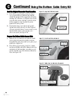
Secure the RF cables to the inside rim of the
baseplate, using the two cable brackets.
Secure the brackets in place using the four M4
screws you removed earlier (see Figure 78).
e.
Attach the supplied cable exit shroud over
the cable entry hole inside the baseplate,
using the two M4 screws you removed earlier
from the cover plate (see Figure 79).
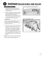
Replace the Logo Plate
a.
Attach the supplied blank logo plate using six
b.
Discard the old logo plate, or save it in case
you need to change the cable routing in the
future.
c.
Weatherproof and seal the cable access hole
in the mounting surface as required.
The baseplate conversion process is
complete! Complete the remaining system
installation steps starting with
.
Figure 78: Cables Secured by Brackets
M4 Screw (x4)
Figure 79: Cable Exit Shroud Installed Over Cables
M4 Screw (x2)
Cable Exit Shroud
Figure 80: Blank Logo Plate (No Cable Slots)
M4 Screw (x6)
Blank Logo
Plate
Continued
Using the Bottom Cable Entry Kit
C
Summary of Contents for tracvision tv8
Page 1: ...TracVision TV8 Installation Guide ...
Page 50: ......