background image

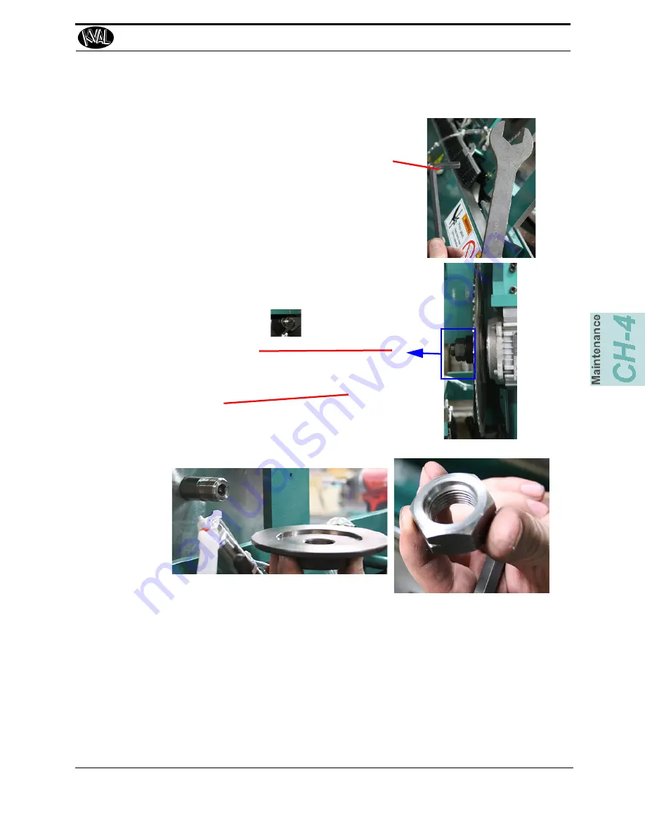
   Replacing Saw Blades

4-15

KVAL 979-2 Operation/Service Manual

5. 

Tools (10 mm Allen Wrench and 36 mm Open End 

Wrench)

6. 

Remove 

Nut 

and 

Blade Clamp Plate

7. 

Carefully lift saw blade off the motor shaft.

8. 

Replace with a new saw blade, ensure blade is flat against 

the motor shaft base.

Note: 

Ensure the Nut is placed with the flat side 

against the blade (See Inset)

9. 

Follow the 

Steps

  in reverse to finish the assembly.

Allen Wrench

Open End 
Wrench

Nut: 

Ensure side pictured is 

against the blade

Outer Saw Washer

Summary of Contents for 979-2

Page 1: ...Innovation Quality Honesty Operation and Service Manual Published 5 24 2019 979 2 Miter Trim Saw System 979 2 Miter Trim Saw System ...

Page 2: ...indows 7 is a registered trademark of Microsoft Corporation All other products are trademarks or registered trademarks of their respective holders all rights reserved Reference to these products is not intended to imply affiliation with or sponsorship of Kval Incorporated Contacting KVAL Customer Service For further information about this manual or other Kval Incorpo rated products contact the Cus...

Page 3: ...user experience with our product that is the manual the machinery the software etc What was easy or difficult to use or to learn If you could change something about the design what would it be Please email your comments and suggestions for improve ment to userexperience kvalinc com NOTE This is not a customer support email link For that please refer to the Customer Service contact information abov...

Page 4: ...KVAL 979 2 Operation Service Manual ...

Page 5: ...er 1 9 Lockout Tagout Air Supply 1 10 Start Maintenance 1 10 Post Maintenance Steps 1 10 Zero Energy to Start Up 1 11 Getting Help from KVAL 1 13 On Line Help 1 13 Product Return Procedure 1 13 Safety Sign Off Sheet 1 16 A Note to the Operator 1 16 Chapter 2 Operation of the 979 2 Operator s Tour 2 2 In Feed Section 2 3 Foot Pedal 2 3 Operators Station 2 4 Operators Station Small Platform Screen 2...

Page 6: ... Screen 2 23 About the Software Start Saws Button Older Machines 2 23 About the Setup Screens 2 26 About Calibration Data 2 26 Running a Reference Cut 2 26 About Motion of Servo Motor 2 26 Entering Calibration Data 2 27 About the Machine Calibration Screen 2 28 About Assigning a Pre set 2 30 About Manual Operation and Chipout Routine 2 31 Diagnostic Screen 2 33 Chapter 3 System IT Administration S...

Page 7: ...ubrication 4 16 Air Line Without Lubricator 4 17 Mechanical Adjustments 4 18 979 2 Guard Placements and Purpose 4 18 Feed Dog Adjustment Procedure 4 20 Chapter 5 Troubleshooting the 979 2 About Motion Control 5 2 Basic Control Circuit 5 2 Typical Positioning Systems 5 4 Troubleshooting Basics 5 7 Using Sensors to Trouble Shoot 5 7 Location of Sensors on 979 2 5 8 Troubleshooting Electrical Problem...

Page 8: ...979 2 Miter Trim Saw System ...

Page 9: ...iew of the 979 2 Miter Trim Saw System 1 2 About this Manual 1 3 Safety First 1 4 Safety Sheet Sign Off Sheet 1 4 Safety Terminology of Labels 1 4 Safety Guidelines 1 4 Lockout Tagout Procedure 1 8 Follow the P R O P E R lockout rule of thumb 1 10 Zero Energy to Start Up 1 11 Zero Energy State to Start Up to Operating State 1 11 Getting Help from KVAL 1 13 On Line Help 1 13 Product Return Procedur...

Page 10: ... measured on the short side The feed hopper may be easily adjusted to accommodate material up to 4 1 2 wide and up to 1 1 4 thick The pieces of casing are fed from the hopper by a reciprocating dog system The feed dog systems on each carriage are tied together with a timing shaft to insure that each piece of cas ing is precisely positioned under the saws every time Each cutting head is equipped wi...

Page 11: ...ion and service and maintenance information It includes identification of machine assemblies power up and power down steps and informa tion about using the user interface The Troubleshooting and Maintenance sections are directed toward qualified service technicians TABLE 1 1 Title Part Number 979 2 Operation and Service Manual DOC 146_3 OPS ...

Page 12: ...amaged or illegible There are three types of warning labels or decals DANGER means if the danger is not avoided it will cause death or serious injury WARNING means if the warning is not heeded it can cause death or serious injury CAUTION means if the precaution is not taken it may cause minor or moderate injury Safety Guidelines In addition to the caution and warning labels affixed to this machine...

Page 13: ... down Never perform any maintenance unless machine is at zero state Never clean the machine while it is running Never walk away from the machine while it is running When the Machine is ON The compressed air system connected to this machine should have a three way air valve for shut off and pressure relief All cylinders on machine are under high pressure and can be very dangerous when activated Bef...

Page 14: ...ocated at different locations Before performing any repairs or mainte nance lockout and tagout must be installed at all locations All maintenance and repairs to electrical circuitry should only be per formed by a qualified electrician Still has power in OFF position Electrical Prior to performing any maintenance repairs cleaning or when clearing jammed debris you must disconnect tag out or lock ou...

Page 15: ...dent If you believe any part or operation of this machine is in violation of any health or safety regulation STOP pro duction It is your responsibility to immediately protect your employees against any such hazard Additional detailed safety guidelines are included in the operating instructions of this manual KVAL will be pleased to review with you any questions you may have regarding the safe oper...

Page 16: ...lock and tag on each disconnect Only each operator may remove their own lock and tag Important When many people are all working on the same machine you will need a multiple lockout device such as the one shown here Follow the P R O P E R lockout rule of thumb P Process shutdown R Recognize energy type electrical pneumatic mechanical etc O OFF Shut off all power sources and isolating devices P Plac...

Page 17: ...air supply and pressure spring tension weight shifts etc 2 Inform all affected personnel of the eminent shutdown and the duration of the shutdown 3 Obtain locks keys and tags from your employer s lockout center 4 Turn off machine See Chapter 2 for power down and power up procedures 5 Turn the disconnect switches on ALL electrical and frequency panels to the OFF position Then push the red tab to po...

Page 18: ...tc are completely removed and that all guards and safety devices are installed 10 Before removing the locks and tags the person who attached them shall inspect the equipment to ensure that the machine will not be put in an unsafe condition when re energized 11 The lock and tag can now be removed only by the person s who placed them and the machine can be re energized 12 The tags must be destroyed ...

Page 19: ...ally when energy is restored Remove Locks Each operator must remove his or her own lock and tag This will ensure that all oper ators are in a safe place when the equipment is started Perform Visual Checks If the equipment is too large to see all around it station personnel around the area and sound the personnel alarm before starting the equipment If your operation is more complex your company s c...

Page 20: ...the key to your lock Proper lockout tagout can save lives limbs and money Help make your work environment safe for you and your fellow workers Be sure to follow the P R O P E R lockout tagout procedures and that those around you do also Close the Cage Gate Verify all cage gates are securely closed Ensure all safety protocols are in effect ...

Page 21: ...ugh Thursday 6 30 AM to 1 30 PM Pacific Standard Time Friday On Line Help On machines with a Beckhoff PLC and an internet connection our service team are able to con nect run and troubleshoot your machine Ask about this procedure when calling are service team Product Return Procedure If you ve contacted Kval for help and it is determined that a return is necessary use the procedure below to return...

Page 22: ...re modified and how With what equipment is the unit interfaced What was the application What was the system environment temperature spacing contaminants etc 3 Call Kval customer support for a Return Material Authorization RMA When you call Have the packing slip or invoice numbers available Have the documented reason for return available 4 Send the merchandise back to Kval Make sure the item s you ...

Page 23: ...Getting Help from KVAL 1 15 KVAL 979 2 Operation Service Manual Page Intentionally Left Blank ...

Page 24: ...follow my company s safety procedures I have read and understand these guidelines Machine Safety Concerns I have been given a tour of the machine and understand all the safety labels E Stops and the actions to take in case of an emergency I will make sure all guards are in place before operation I will turn off the compressed air before loading hardware staples screws etc I will turn off the elect...

Page 25: ...Safety Sign Off Sheet 1 17 KVAL 979 2 Operation Service Manual ...

Page 26: ... Light Panel 2 8 About Sensors 2 9 Quick Start 2 10 Powering Operations for the 979 2 2 12 How to Power Up the 979 2 2 12 Home the 979 2 2 13 How to Power Down the 979 2 2 14 Emergency Shutdown and Recovery 2 14 About Modes 2 15 Mechanical Set Up 2 16 Description of User Interface Screens 2 18 Screen Selection Menu Map 2 18 Screen Selection Menu Map Small Platform Screen 2 19 Machine Feed Back 2 2...

Page 27: ...our of the 979 2 Miter Trim Saw System machine FIGURE 2 1 Identification of Key Assemblies of 979 2 In Feed Operator s Station Safety Curtain Servo Motor and Ball Screw Out Feed Right or Movable Head Left or Fixed Head Safety Curtain Hopper Staging area and Feed In Electrical Panel Foot Pedal Stop Feed ...

Page 28: ...to cylinders Air Input System Air Filter PSI Adjust and lubricator Operator Station Hopper and Staging Area Foot Pedal The foot pedal controls the flow of the board through the machine Press the right pedals to feed the product through the machine If the hopper is stacked the product will feed through automatically Or the quantity set on the main screen Press the left pedal to stop the machine Thi...

Page 29: ...e Screens on page 2 20 and Quick Start on page 2 12 for more information FIGURE 2 3 Operators Station with touch Screen Interface Operators Station Small Platform Screen A reduced size screen has been added to the 979 2 Start SN 17 146 061 The menu choices and controls are similar but have changes in format See Screen Selection Menu Map Small Plat form Screen on page 2 21 FIGURE 2 4 Reduced Size S...

Page 30: ...he machine The finished product is fed out for on the back side of the machine Danger Never mechanically bypass the Safety Curtain or enter the cutting area avoiding the Safety Curtain Serious injury could occur FIGURE 2 5 Out Feed Key Parts Safety Curtain Safety Curtain Out Feed Area Fin ished Product is fed out of the machine Electrical Panel ...

Page 31: ...ain Electrical Panel Supplies voltages to the machine Contains the PLC Programmable Logic Controller Contains servo drives to interact with the servo motors Axis and Lock Loca tion in the front and back sections VFDs Variable Frequency Drives to interact with hinge and faceplate rout ers width adjust motors and feed motors VPN Router added to connect with factory intranet to internet KVAL Ser vice...

Page 32: ...efore VPN FIGURE 2 7 Overview of Main Electrical Panel and High Frequency Panel The Thermal Resistors are 30 ohm resisters that help the carriage stop quickly Main Electrical Panel PLC 110 V 24 V Terminals High Voltage Section Input Output Terminals VFD Section Servo Drive Control Trans former Contactor and Over load Circuit ...

Page 33: ...he factory must have access to the internet to use this feature To use the VPN 1 Ensure your company has a connec tion to the Internet Contact factory IT technician 2 Have issue organized to inform KVAL technician 3 Contact KVAL Service and notify that you are using a VPN on a 979 2 4 Tell the technician the issue 5 When ready push the VPN button until the button lights up 6 The technician can con...

Page 34: ...sed of an EZ Screen emitter and receiver The emitter has a row of synchronized light emitting diodes LEDs that send signals to the receiver The receivers have a a matching row of synchronized photo detectors that read the signal from the emitter When the signal is blocked of any beam the machine stops To continue machining push the Start button Important The EZ Screen system is aligned at the fact...

Page 35: ...ight illuminates when the Control Transformer is pulled out and the power is working on secondary side of transformer Overload Relay The overload circuit is working when light is on E Stop The back gate is closed and Frame E stop is not acti vated when this light is on 24VDC light comes on once the ACR is latch and the 24VDC power Supply is working Stop This light will be on if Machine Stop button...

Page 36: ...o Eye 0VDC is sent to the PLC As a result any of the photo detectors output equals 0VDC when the trim is sensed The Proximity Sensor detects metallic objects without touching them An inductive proximity sensor consists of a coil and ferrite core arrangement an oscillator and detector circuit and a solid state output The ferrite core and oscillator create a field generating out the front of the sen...

Page 37: ... How to Power Up the 979 2 on page 2 14 3 Home the 979 2 See Home the 979 2 on page 2 15 4 Set the machine up for the chosen parameters See Mechanical Set Up on page 2 18 5 Select the cut mode 6 Select the desired preset button 7 Select quantity of boards to cut Enter the cut length if different than the pre set 8 Select type of cut Note KVAL strongly recommends using the Wide Jamb selection on cu...

Page 38: ...t Saws Button to get the saws running Note Some machines may have a software button to activate the saws instead of the mechanical button If so press and hold the Saws Off button until the saws start Button displays Saws Active 13 Start production by pressing the Start Sequence right the foot pedal If finished with production and shutting the machine down see How to Power Down the 979 2 on page 2 ...

Page 39: ... buttons are out Note A pop up is displayed on the user screen if an E Stop is pressed The pop up will indicate which E Stop has been activated 3 Make sure the electrical disconnect the electrical cabinet is turned to the ON posi tion 4 Switch the green CONTROL TRANS FORMER switch to the ON position It should light up 5 Push the green START MACHINE button to boot up the machine Control Transformer...

Page 40: ...ference Press the Home button on the Main Screen touch screen Note Safety Curtain Startup Danger Never mechanically bypass the Safety Curtain or enter the cutting area avoiding the Safety Curtain Serious injury could occur When power is applied to the EZ Screen emitter and receiver each sensor will conduct self tests to detect critical internal faults and prepare for operation If no faults are det...

Page 41: ...rical cabinet to OFF this helps reduce possible damage resulting from power surges from electri cal storms Emergency Shutdown and Recovery There are emergency shutdown E Stop switch located at key points around the machine The E Stop switches are to be used when the machine is out of control or is about to damage personnel or equipment When an E Stop switch is activated power to the machine is kil...

Page 42: ...ated below See About Adjusting Each Cut Mode on page 2 30 for information about selecting the dimensions for the cut Right Head Left Head 45 deg 45 deg Left Head Right Head Into machine 45 deg 00 deg Left Head Right Head Into machine 00 deg 45 deg Left Head Right Head Into machine 00 deg 00 deg Left Head Right Head Into machine ...

Page 43: ... station prepare the machine to process the stack 1 Adjust both back hopper stops for a hopper width of roughly 1 8 inch larger than the stock 2 Adjust both front hopper stop s height to clear the stock by roughly 1 8 inch Adjustment Bolts for Height Rear Hopper Stop Front Hopper Stop Note Use a 1 2 wrench to Adjust the Bolts ...

Page 44: ...the valve must be slid toward the input side of the machine For stock greater than 3 inches the valve must be slid toward the out feed side of the machine Mechanical Set Up 2 19 KVAL 979 2 Operation Service Manual 6 Load the Hopper 7 On the Touch Screen press and hold the Start Saw button to start the saws 8 Press the feed in foot pedal to start the machining of the product NOTE Wide jamb mode has...

Page 45: ... a touch screen to control the trim cutting process auto run manually run the trim store trim pro files and use diagnostics to help troubleshoot the 979 2 Screen Selection Menu Map FIGURE 2 9 Screen Selection Below are the menu selections for the 979 2 See About the Manual Parameter Menu on page 2 25 See Main Screen on page 2 23 See About Calibration Data on page 2 27 See About Assigning a Pre set...

Page 46: ...enu operation is slightly changed The main change is there are more jump pages to utilize The changes are defined in the figure below This platform is described in this chapter See About the Manual Parameter Menu on page 2 25 See Diagnostic Screen on page 2 34 See Main Screen on page 2 23 See About Calibration Data on page 2 27 See About Assigning a Pre set on page 2 31 Jump to next page of stored...

Page 47: ...vo Store Program To allow the operator to make changes to parameters turn the Set Up Lock to the On position When this key is in the Off position the parameters are locked out No changes to the parameters may be made in the off position Set Up Mode This setting allows technician to stop the saw from running if performing calibration on the machine The technician can feed in a trim board with the f...

Page 48: ...m this screen all the basic user inter face controls are available to run a cut on a trim board FIGURE 2 11 Main Screen About the Software Start Saws Button Older Machines Some previous machines may have a software button to start the saws This button was replaced by a mechanical Start Saws Button For description of the mechanical button Jump Buttons ...

Page 49: ...after Reset Machine About the Preset Selection Button Group Pressing a preset button calls a stored length of the casing to be machined There are 56 stored presets for each cut mode The cut modes are 45 deg 45 deg 45 deg 00 deg 00 deg 45 deg 00 deg 00 deg To choose a preset 1 Select the cut mode The cutting heads will move to 45 deg or 0 deg depending on choice 2 Select the desired preset button S...

Page 50: ...e dis played in the box 4 Push and hold the black button to move the Right Head into position The machine is now primed to perform See Description of User Interface Screens on page 2 20 for full operation steps To assign a preset to the button See See About Assigning a Pre set on page 2 31 for more information About the Manual Parameter Menu If the preference is not to use the preset buttons manua...

Page 51: ...continue machining 2 Locate the Saws bottom on the lower left had corner of the main scree 3 Press and hold the SAWS OFF button for 3 seconds 4 The button will display SAWS STARTING you will hear the machine starting up Warning The Saws are running now DO NOT put your hands near the saw blade 5 The machine is ready to start working when SAWS ACTIVE is displayed on the button 6 After machining is c...

Page 52: ...e Cut If you notice any changes in the cut locations run a reference cut Run a known good profile After the trim is machined measure the results The Base is the start up reference The differences between the template and the measured either positive or negative are entered into the Offset entries The Actual is the combination of the Base and the Offset entries which is the final result About Motio...

Page 53: ...urement b If the board is too long subtract the difference between expected results and the measurement 3 If it is correct go back to the calibration screen and click Combine with Offset to combine offset and base to complete the calibration 4 Click the Clear Offset button to clear any incorrect number in the Offset box 5 Run a second cut and recheck the result 6 If the result is off repeat steps ...

Page 54: ... The Setup button leads to the Machine Calibration screen In this screen you can perform machine calibration of the following Individual parameters for each cut mode System wide or all cut modes as a set FIGURE 2 12 Setup Menu Miter Stop Adjustments are an Optional choice for machines with Miter Option ...

Page 55: ...erence between the expected results and enter into the off set box See on page 2 28 for more detailed instructions 45 deg 45 deg 00 deg 45 deg 45 deg 00 deg 00 deg 00 deg Check Length Check Length Check Length Check Length About the Miter Stop Option If a discrepancy is observed on the miter stops use this menu to adjust stop positions About Adjusting System Cut Modes If all the lengths are out of...

Page 56: ...set button until it turns green 3 Push the Modify Pre sets button to go the Pre set menu 4 At the Pre set menu enter a title that will appear on the main screen button 5 Enter the length in either decimal or fractional measure ments 6 Select the Save button 7 Select the Main button to go back to the main menu The previ ously selected button will have the title and length Small Plat form Screen ...

Page 57: ...screen is can be used in troubleshooting checking cut specifications and maintenance This page offers manual control of the saw carriage and running a Chipout Routine FIGURE 2 13 Manual Operation Screen Press the Exit Application button to close the user screen and return to the Main Screen Enter the speed desired and press and hold the Close or Open Button until the Saw Car riage moves to the des...

Page 58: ... Block on page 4 13 3 Jump to the Manual Screen 4 Press and hold the Chipout Routine Button to put the machine into chipout mode 5 While holding the Chipout Routine Button Press the Start Saws Button to start the saws and bring down to the chipout block to cut it Release the Start Saws Button to detract the saw away from the chipout block 6 After burn in is completed release the Start Saws Button ...

Page 59: ...uble shooting by associating the error code to machine sections or functions The top line will have the most current routine that is running If the machine issue can not be resolved call KVAL Inc 1 800 553 5825 Have any error code that is displayed ready to give the KVAL representative This will aid in troubleshooting and shorten down time FIGURE 2 14 Diagnostic Screen ...

Page 60: ...Notes ...

Page 61: ...er that supplies the user interface and controls the operation of the machine With the controller KVAL can remotely help troubleshoot your machine Chapter 3 at a Glance System IT Administration 3 2 About the 979 2 Computer 3 2 Connections on the PLC 3 2 Backing up the Computer 3 3 About Remote Connection to KVAL Service 3 3 ...

Page 62: ...removable Compact Flash card from which it boots The controller uses a Windows 7 operating system with TwinCAT 2 automation software to create the PLC and Motion Control method Interface modules include A smart power supply to connect to EtherCat terminals This supply contains a LCD to display system and user messages A DVI USB module to connect to the user interface An Ethernet module to connect ...

Page 63: ...crash Click the Back Up Icon on the Desktop to back up your data The data is stored in a backup folder in your Windows directory It is recommended to set up a back up schedule to save your data on a regular occurrence The KVAL service team would be happy to help If any questions occur contact our service team at 800 553 5825 or at www kvalinc com ...

Page 64: ...System IT Administration 3 4 KVAL 979 2 Operation Service Manual ...

Page 65: ...ypical Lucubration Kit 4 5 Lubrication Requirements 4 6 Pillow Block Bearing Housings 4 6 Flange Bearing Housings 4 7 Ball Rail Bearing 4 7 About Taper Bearings 4 8 Tapered Bearing Housings 4 8 Ball Screw Nut 4 9 Ball Screw Drive Assembly 4 9 Pulley and Idler Shafts 4 10 Lubrication Points on the 979 2 4 11 Lubrication Points Heads 4 12 Replacing the Chipout Block 4 13 Replacing Saw Blades 4 15 Re...

Page 66: ...machine Clean Blow out dust collection cans 600 Cycles Inspect Air Pressure Gages Adjust if necessary to the proper PSI located on the label Inspect Inspect Air Filter Water Traps Empty if necessary Inspect Inspect the Tooling for wear Drill Bits Cutting Tools Screw Driver Bits Lubricate Lubricate the inside the waste cut chutes with a light coat of dry silicone spray Clean Empty Dust Collection U...

Page 67: ... abrasions Lubricate Clean and lubricate all slides and cylinder rods with dry silicone spray Lubricate Lubricate all bearing shafts with silicone and clean rag Clean Clean Hex Shaft with WD 40 and a 3M Scotchbrite pad Wipe dry with a WD 40 coated rag 72 000 Cycles Inspect Inspect all nuts and bolts for tightnesses Tighten is necessary Inspect Check that there is a smooth transition with a door fe...

Page 68: ...ollowing This machine is tuned an calibrated at the factory If any of these conditions are changed timing accuracy or damage may occur during the machine process Do not adjust air PSI above or below factory settings Do not adjust any and all flow controls from factory settings Do not remove shim stock ...

Page 69: ...Block Bearing Idler Shaft Flange Block Bearing Ball Screw Every 80 Hours of Machine Operation Tapered Bearing Once a Year Air Line Lubricator One drop of oil every 2 or 3 cycles Check the lines every week to two weeks Note Some CNC Machines drop every 5 10 cycles Either lubricant listed below is approved to use KVAL P N SYSLUBG Chevron AW Hydraulic Oil 32 G C lubricants light AW R O Mobile DTE 24 ...

Page 70: ...rk fitting is basically a valve that opens under pressure to allow lubricant to pass through a channel and be forced into the voids of the bearing When the pressure stops the ball returns to its closed position The ball excludes dirt and functions as a check valve to prevent grease escaping back out of the fitting The ball is almost flush with the surface of the fitting so that it can be wiped cle...

Page 71: ...r reliable operation FIGURE 4 17 Flange Bearings Ball Rail Bearing Ball Rail Bearings are linear bearings that are attached to positioning rails In most cases the bear ings are attached to assemblies to move them in the X Y or Z direction FIGURE 4 18 Ball Rail Bearings Greasing Flange Bearing Bearing Housings Approximatively 1 Gram one pump from grease gun of Dura Lith Grease KVAL P N Lube EP 2 Ev...

Page 72: ...is such an asset that the bearing blocks often require little maintenance for the life of the machine FIGURE 4 19 Sample of Tapered Bearing Tapered Bearing Housings The taper bearings differ from other machine bearing assemblies in that they are in a sealed envi ronment To identify a Tapered Bearing Housing look at the enclosure and verify there are seals between the screw and the housing FIGURE 4...

Page 73: ... Typical Ball Nut Ball Screw Drive Assembly Including the Ball Screw Nut other types of bearings may be included on the assembly The figure below shows a typical Ball Screw Drive Assembly FIGURE 4 22 Ball Screw Drive Assembly Approximatively 1 Gram one pump from grease gun of Dura Lith Grease KVAL P N Lube EP 2 Every 80 hours of operation Ball Screw Nut Housing Ball Screw Drive Greasing Ball Screw...

Page 74: ...he door in and out of the machine Each pulley contains an idler shaft that has a zerk fitting to apply grease An opening in the idler shaft dispenses grease to the inner diameter of the pulley Pulley in Action Breakout of Pulley Assembly Grease IN Grease Out Note It is important not to overfill the Idler Shaft Avoid get ting excess grease on the belts Idler Shaft ...

Page 75: ...s when working on this machine See chapter one for safety information Lubrication Points on the Frame of the Machine Identify zerk fittings and apply EP 2 grease Find the X Y and Z axis rails to identify bearings Some bearings may be difficult to get access to Use an extender to reach tight areas Make sure that Lockout Tagout has been performed before maintenance This is a view of the frame from t...

Page 76: ...ind the X Y and Z axis rails to identify bearings Some bearings may be difficult to get access to Use an extender to reach tight areas Make sure that Lockout Tagout has been performed before maintenance FIGURE 4 24 Head Lubrication Points Fixed Head Movable Head Movable Head Bottom Linear Bearings X4 Linear Bearings X4 Linear Bearings X4 Tools ...

Page 77: ...ou must disconnect tagout or lockout the electrical and air pressure systems This should be done in accor dance with applicable state and or federal code requirements 1 Perform Lockout Tagout See Lockout Tagout Procedure on page 1 9 2 Remove the 8 screws to detach the covers located on the Fixed Head and the Mov able Head Set them aside Chip Block Located Under the Saws 4 Screws 4 Screws 3 Locate ...

Page 78: ...Procedures when working on this machine See chapter one for safety information 1 Perform Lockout Tagout 2 Remove Front Cover 3 Loosen Knob on the Saw Access Cover and Open it Access Cover Front Cover Remove the Saw 4 Remove Cylinder Assembly and lay down out of the way Cylinder Assembly Move Cylinder Aside Remove 2 bolts ...

Page 79: ... 7 Carefully lift saw blade off the motor shaft 8 Replace with a new saw blade ensure blade is flat against the motor shaft base Note Ensure the Nut is placed with the flat side against the blade See Inset 9 Follow the Steps in reverse to finish the assembly Allen Wrench Open End Wrench Nut Ensure side pictured is against the blade Outer Saw Washer ...

Page 80: ...ers delivers the lubricated air to valve banks and air cylinders FIGURE 4 25 Typical Air Line Filter and Lubrication System Adjusting the Air Line Lubricator Using the knob on the top of the lubricator adjust until one drop per every other cycle is used as observed through sight glass Shop Air Input Air On Off Muffler Filter purge Pressure Gauge with adjust Clean Dry Air CDA to Air Blow Off Lubric...

Page 81: ... Harmony 32 To prime the lubricator find an air line on the carriage section of the machine that is energized and disconnect it allowing the air stream to bleed air pressure away from any persons Direct the air stream at the machine so you can see when there is an oily film blowing out of the air hose Repeat this same procedure for the back section and other trouble areas It is recommended to chec...

Page 82: ...s toward the end s of the machine Removal of the saw assembly guard is a two person job Never attempt to remove the guard by yourself Belt Guard Never Access The Belt Guard While Power Is On Located on both saw carriages INSIDE the saw assembly guard toward the outboard front of the saw assembly The belt guard protects the operator from getting hands caught between the belt and the belt pulleys Th...

Page 83: ...ts are located in two rows of four bolts on the ends of the guard s toward the front and back of the feed dog assembly Kerf Blade Guard for optional Kerf Saw Never Access The Kerf Blade Guard While Power Is On Mounted directly over the kerf blade s on both kerf routers located on either end of the 979 2 The kerf blade guard is designed to protect the operator from the kerf blade whether or not the...

Page 84: ...structions in Chapter 1 11 Holding the right angle of a T Square against the Fixed Head Dog plate adjust the forward feed stops so both the fixed head middle feed dog and movable head feed dog and the alignment mark all line up Fixed Head Dog Plate Fixed Head Fixed Head Forward Feed Stop Movable Head For ward Feed Stop Movable Head Dog Plate Feed Movable Head Plate T Square Fixed Head Mid dle Feed...

Page 85: ...d dog plates agents the Feed Reverse stops 13 Adjust the Feed Reverse stop for a gap of 8 15 16 between the forward edge of both Feed Dog Plates and the Feed Forward Stop 8 15 16 Feed Forward Stop Feed Dog Plate Feed Reverse Stop 14 Reinstall the inside covers 15 Remove Lockout Tagout 16 Continue production ...

Page 86: ...Mechanical Adjustments 4 22 KVAL 979 2 Operation Service Manual ...

Page 87: ...ems 5 9 If the Power Stops During Normal Operation 5 9 Troubleshooting with the Status Light Panel 5 10 Control Power Light OFF 5 12 Overload Relay Light OFF 5 13 E Stop Light OFF 5 13 Stop Light OFF 5 13 Start Light OFF 5 14 24VDC Light OFF 5 14 About VFD Troubleshooting 5 15 Error Checking on the Variable Frequency Drives 5 15 Using the Reset Buttons 5 15 Troubleshooting the Air Cylinders 5 16 A...

Page 88: ...out Incremental Incremental motion control is used when the load is required to be moved with high accuracy to multiple locations sometimes in multiple directions axes A typical KVAL usage for this sys tem is a computer controlled router in a door light machine where there is great variety in the cut size shape and location Basic Control Circuit This section describes a basic control circuit The F...

Page 89: ... waiting for the OK to move command Sends the positioning instructions to the positioning system Listens to the positioning system for position status if there is a feedback loop Tells the machine s other subsystems when the move process is completed Examples A PLC or a dedicated motion control board Positioning System Moves the load Examples A motor or a pneumatic cylinder The Position Feedback P...

Page 90: ...heavy motor currents The figure below shows a block dia gram of a typical contactor circuit with typical voltages FIGURE 5 28 Common contactor Block diagram PLC Output Fuse s Line Voltage Power Contactor Control Coil Input Power Input Power Output Control Circuit Common ON Should measure Control Voltage 120 VAC here Should measure Line Voltage here Should measure Line Voltage here Line Voltage her...

Page 91: ...diagram of a typical motor drive circuit with typical voltages FIGURE5 29 Common Motor Drive Control Common Motor Drive Control PLC Output Fuse s Line Voltage Motor Power Motor Power Input Output Power Control Circuit Common ON Should measure Control Voltage 24 VDC here Should measure Line Voltage here Should measure Line Voltage here ON Drive STF Forward RL STR Revers 2 SD COMMON OFF OFF OFF Run ...

Page 92: ...lamping a door FIGURE5 30 Common Pneumatic Block Diagram Common Motor Drive Control PLC Output Fuse s Line Voltage Motor Power Motor Power Input Output Power Control Circuit Common ON Should measure Control Voltage 24 VDC here Should measure Line Voltage here Should measure Line Voltage here ON Drive STF Forward RL STR Revers 2 SD COMMON OFF OFF OFF Run 300 Run Light should be ON Should display th...

Page 93: ...pen when door was being fed in Is the router not cutting Is the cut out of specification Verify Verify or analyze the subsystem assembly that is responsible for the issue For example How is the subsystem supposed to work What is keeping the subsystem from working Check the Positioning System Follow the circuit from the Controller output to the Load and check for component failures Using Sensors to...

Page 94: ...ignation represents an output from the PLC FIGURE5 31 Location of Sensors Top View 979 2 Sensor Left Board Straight Sensor Home Sensor Right Board Straight Sensor Close Limit Sensor Open Limit Left Head Switches 45 degrees Saw Retracted Saw Extended Kerf Saw Retracted Kerf Saw Extended Right Head Switches 45 degrees Saw Retracted Saw Extended Kerf Saw Retracted Kerf Saw Extended Switch Feed Dog Re...

Page 95: ...atching the lights turn on or off Compare the lights on the IDEC or Beckhoff controllers to the electrical print to determine what systems are being affected If the Power Stops During Normal Operation 1 Check that the input power disconnect switch is not turned off 2 Check that all of the emergency stop buttons are in the normal position 3 Check the Six Lights on the Electrical Panel See Troublesh...

Page 96: ...uck motors jammed chain blocked photo sensors etc Note If a solenoid valve is suspected and not cleared in the air checks section see it can be electrically jumped to check operation Troubleshooting with the Status Light Panel The Status Light Panel is located on the Electrical Panel All six lights are illuminated when the system is in proper working order The lights turn on in a sequence and will...

Page 97: ...tem A on page 5 12 STEP 2 Overload Relay Amber If light is OFF go to item B on page 5 13 STEP 3 E Stop Amber If light is OFF go to item C on page 5 13 STEP 4 Stop Amber If light is OFF go to item D on page 5 13 STEP 5 Start Amber If light is OFF go to item E on page 5 14 STEP 6 24VDC Green light is OFF go to item F on page 5 14 The sequence that the lights turn on are as follows 1 Control Power Am...

Page 98: ... into the top of the Control Transformer replace the Control Transformer 6 If there is power at the Control Transformer check the wiring of the black and white wire going from the Control Transformer to the 110 VAC Terminal Strip 2 Is the Disconnect Switch on the main electrical cabinet set to ON Switch 3 Is there 208 220 440 or 575 VAC to the top side input of the Control Trans former If not chec...

Page 99: ...p Trip Indicator Factory Set Current Rating Adjust E Stop Light OFF Check to see the if any E Stop buttons are pulled out NOTE Location and quantity of E Stop buttons var ies depending on customer need Typical locations for E Stop buttons are near the Rear Access Gate and near the Tool Changer Access Gate Stop Light OFF Check for 110 VAC between 2 and 4 If there is voltage press the Start button I...

Page 100: ...here those wires were disconnected If no voltage Check the input side for 110 VAC If no 110 VAC check the fuse If there is 110 VAC and no 24VDC replace the 24VDC Power Supply If there is 24VDC Reconnect the output wires to the 24VDC power supply Trace the output wire to the DC terminal block Disconnect all 24V positive wires from the DC from the DC terminal block except the output wire from the 24...

Page 101: ... shut down On some options reset buttons are located on the door of the VFD panels The button contains the VFD function printed on the button If a VFD is tripped to OFF the button will be lit To reset a VFD 1 Push lighted button to reset the indicated motor c If the button light turns off continue with production d If the button stays lit find the source of the down motor printed on the but ton Fo...

Page 102: ...on the retract port this regulates the air flow exhausting from the cyl inder and the opposite is true for the retract motion 1 Check the air pressure to the machine 2 Check the flow controls to see that they are adjusted correctly and to the proper specifications 3 Check for any obstructions to the cylinders such as screws or a misplaced tool etc FOLLOW ALL SAFETY GUIDELINES AND SIGNS DURING THIS...

Page 103: ...a rebuild kit or a new cylinder c If the valve is not receiving an electrical signal for instructions It might be necessary to call in a specialist or check with KVAL customer service at 1 800 553 5825 5 If an Air Leak is coming from an exhaust port on the solenoid air bank a Check the solenoid for the manual override If the solenoid has a manual over ride you can push each of the buttons one at a...

Page 104: ...ding on the model of limit switch on your machine the pre travel amount of movement from the limit switch arm s resting position to the position at which the switch actuates with a click is either 5 or 20 degrees If the arm is moved to the full extent of its travel and you do not hear the limit switch click the switch needs to be adjusted Use the set screw on the limit switch arm and adjust the ar...

Page 105: ...Notes ...

Page 106: ...ion2 16 e stop light description2 10 EtherCat smart power supply3 2 terminals location3 2 ethernet module connection to servo amplifiers3 2 F flange block bearing maintenance schedule4 5 front section status feedback2 22 G gear box maintenance schedule4 5 H hinge spec group description2 25 home button description user interface2 24 using2 15 I inductive proximity sensor2 11 internet access locatio...

Page 107: ... to Kval1 13 S safety guidelines1 4 Safety Sign Off Sheet Safety Concerns1 16 sensors descriptions5 7 location on frame5 8 troubleshooing5 7 types2 11 voltage levels2 11 service center contacting information1 13 servo positions feedback2 22 setup screens2 26 six light panel description2 10 sequence list2 10 start light description5 14 start light description2 10 start machine button power up2 14 s...

Page 108: ......

Page 109: ......

Page 110: ......

Page 111: ......

Page 112: ...partment Kval Incorporated 825 Petaluma Boulevard South Petaluma CA 94952 Contacting KVAL Phone and Fax In the U S and Canada call 800 553 5825 or fax 707 762 0485 Outside the U S and Canada call 707 762 7367 or fax 707 762 0485 Email service kvalinc com http www kvalinc com ...

Reviews: