-24-
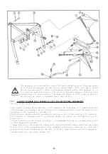
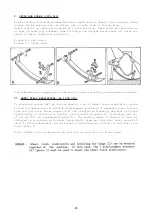
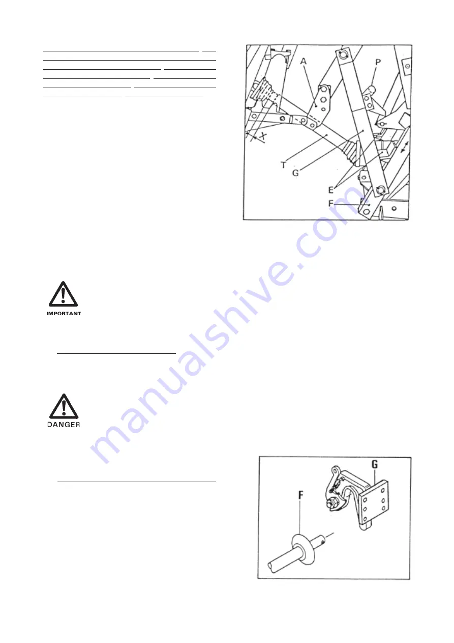
In addition, with this combination, the
stops (E)* must be fitted and correctly
adjusted on the front frame (F) in order
to protect the PTO shaft (T) from being
subject to excessive angles and to avoid
the sliding tubes butting together.
Therefore, when first mounting the
machine, proceed as follows :
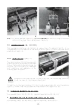
- Connect transmission (T)
- Progressively lift the combined ma-
chine up to the maximum overlap of the
transmission tubes, at the same time
ensuring that there is always a safety
clearance (X) of 1-2 cm (1/2"-1").
- Position and lock the stops (E) on the
front frame (F) so that they come into
contact with the lower arms (G) and
therefore limit the lifting height.
The manoeuvrability of the rear hydraulic linkage can then be made with total safety.
* Set of stops : No 1207 690
The gearbox is fitted with a rear PTO shaft which turns at the same speed
(rotational frequency) as the tractor drive shaft. This rear drive shaft
should not be used to drive a secondary machine while the gearbox is in
its neutral position (due to the risk of gearbox damage resulting from
inefficient oil circulation). The rear PTO shaft (1 3/8" 6 spline profil)
should not be used to transmit more than 50 HP.
c) Maintenance of the linkage
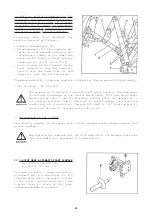
Periodically grease the different pivot points equipped with grease nipples (ten
grease nipples).
When parking the combined unit (EL 100 N seed drill, for example) make sure
that the additional implement is lowered first.
IV 3-POINT SEMI-AUTOMATIC FRONT LINKAGE
(no 1207110 for cat. II,
no 1207120 for cat. III)
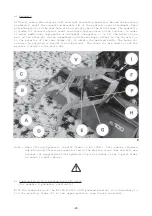
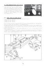
The semi-automatic linkage includes an
attachment bar (F) and two hooks (G). Fit
the attachment bar to the lower link arms
of the tractor and the hooks (G) to the
3-point frame in place of the lower
standard attachment brackets.
Summary of Contents for EL 100 N
Page 1: ...ASSEMBLY OPERATOR S MANUAL EL 100 N POWER TILLER N 95458 A GB 12 1999...
Page 10: ...8...
Page 18: ...16...


