-26-
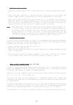
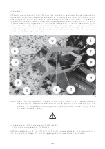
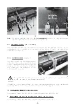
Note : To ensure maximum stability, it is recommended to also fit reinforcing arms
(M) with the wheel track eradicators (photo 5).
VII. REINFORCING KIT (No. 120 8010)
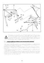
This equipment reinforces the fixation of support bar (T) (photos 5 and 7). It is
recommended to fit in addition to the levelling bar (photo 7) and/or the wheel track
eradicators (photo 5).
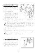
VIII. LEVELLING BAR (photo 7)
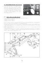
The levelling bar (N) can be mounted at
either the front or the rear of the Power
Tiller. The height can be adjusted by the
two pins (K) for working in different
soil conditions and depending on the
working depth required.
Always fit the levelling bar in such a way that the angled edge faces the
front (as seen in the forward direction).
In addition to the levelling bar, fit the 2 reinforcement arms (M) onto the machine
(photo 7). These arms ensure maximum reinforcement of support bar (T).
IX. SIGNALLING ELEMENTS (No 120 9010)
See assembly sheet (No 023 364 00) supplied separately with the kit.
X. ATTACHMENT KIT FOR DA ACCORD SEED DRILL (No 121 6070)
See assembly sheet (No 922 4062) supplied separately with the kit.
Summary of Contents for EL 100 N
Page 1: ...ASSEMBLY OPERATOR S MANUAL EL 100 N POWER TILLER N 95458 A GB 12 1999...
Page 10: ...8...
Page 18: ...16...


