background image

30

EN

05/2016

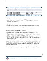
11. Type key

Key 1 ( for process connection other )

 -

Size

Key 1

 -

Version

Key 1 ( for process connection flange )

 -

Flange connection

Key 1 ( for process connection other )

 -

Other process connection

Key 1.2 ( only for flange )
… / 

 / … -

Flange connection

Key 1.3 ( only for flange )
… / … / 

 -

Flange connection

Key 1.1 ( only for flange )

 / … / … -

Flange connection

Threaded connection size
Welding stub end size

Flange pressure rating

Flange facing

Flange nominal bore

Flange according to EN
Flange according to ANSI
Flange according to …
Flange according to drawing

Female thread G 
Female thread NPT
Male thread G 
Male thread NPT
Welding stub end
Without process side connections ( Code 3 not applicable )


BNA

1

BMG

1

ACS1A

1

ACS1B

1

ACS1C

1

ACS1D

1

ACS2

1

ACS3

1

ACS4

1

FE

1

FA

1

F

1

FS

1

GM

1

NPTM

1

GN

1

NPTN

1

SE

1

OS

1

Code 3

Code 3

Code 2

Code 1

Code

1

2

3

4

5

6

7

8

Key

1

-

1

-

1.1

/

1.2

/

1.3

-

1

/

2

/

3

/

4

/

5

/

6

/

7

/

8

-

1

-

1

-

1

/

2

/

3

-

1

-

Example

BMG - FE -

25

/

16

/

B1

- ALF /

TP43B

/

V

/ K15 /

EXIAG - DU - M… - V

/ 60 /

2

-

-

Example

Black = not possible according to Atex / 

Blue = possible according to Atex Exia

 / 

Blue

1

 = possible according to Atex Exia and Exd

 / Black

1


= possible according to Atex Exd

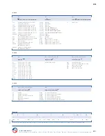
Bypass level indicator
Bypass level indicator with Level transmitter
Bypass complete solution for GWR system, chamber ≤ DN50 / 2“
Bypass complete solution for GWR system, chamber DN65 / 2.5“ 
Bypass complete solution for GWR system, chamber DN80 / 3“ 
Bypass complete solution for GWR system, chamber ≥ DN100 / 4“
Bypass complete solution for GWR system

Heinrich Kübler AG

Ruessenstrasse 4 | CH-6340 Baar | T41 (0)41 766 62 62 | Fax +41 (0)41 766 62 63 | E-Mail [email protected] | Internet www.kubler.ch

Summary of Contents for BYPASS LEVEL INDICATOR DIFFERENTIAL COMPENSATED

Page 1: ...ERENTIALKOMPENSIERT BYPASS LEVEL INDICATOR Technische Dokumentation Seite 2 19 Technical Documentation Page 20 35 Heinrich K bler AG Ruessenstrasse 4 CH 6340 Baar Telefon 41 0 41 766 62 62 Fax 41 0 41...

Page 2: ...8 Hinweise f r Ex Magnetschalter 8 9 Niveau Messwertgeber 9 9 1 Funktionsprinzip des Niveau Messwertgeber 9 9 2 Elektrischer Anschluss der Niveau Messwertgeber 9 9 3 Achtung 9 9 4 Wartung des Niveau...

Page 3: ...entialkompensiert siehe Seite 13 wird mittels Prozessflansche 1 und geeigneter Dichtung 2 seitlich an den Beh lter angeschraubt Es ist darauf zu achten dass die Dichtfl chen und Dichtungen mechanisch...

Page 4: ...rsehen 5 Hinweise 4 Gefahrenhinweise Es darf keine provisorische Installation durchgef hrt werden wenn Komponenten oder ganze Ger te fehlerhaft oder falsch sind resp wenn Komponenten fehlen Ger te und...

Page 5: ...en von Teilen der Kategorie 1G d rfen die Legierungsanteile insgesamt die folgenden Werte nicht berschreiten 10 f r Aluminium Magnesium Titan Zirkonium oder 7 5 f r Magnesium Titan Zirkonium Der Bypas...

Page 6: ...r Grenzwerte 8 Magnetschalter 8 2 Elektrischer Anschluss der Magnetschalter Der Betreiber muss sicherstellen das Ger te die einen Erdungsanschluss aufweisen geerdet werden Ger te mit Anschlusskabel si...

Page 7: ...bei den Ger ten um Messsysteme mit elektronischen Komponenten handelt Dementsprechend sind die Ger te zu verpacken Das u ere Verpackungsmaterial Holz Kartonkisten usw sind mit Gefahrenhinweissschilder...

Page 8: ...l Einbau mit Temperaturschaltern Temperaturklasse Oberfl chentemperatur Umgebungstemperatur Ex ia llC Ex tb IIIC IP6 Ex d llC Ex tb IIIC IP6 Ex mb ll Ex tb IIIC IP6 Basis Option N R Basis Option N R B...

Page 9: ...udichten und der Deckel des Anschlussgeh uses gut zu verschlie en Messumformer Niveau Messwertgeber mit eingebautem Kopfmessumformer sind nach dem Anschlussschema im Anschlussgeh use anzuschlie en Die...

Page 10: ...eingesetzt werden Es d rfen keine mechanischen St sse durch das Medium auf das Ger t einwirken Bei Entz ndungs und Explosionsgefahr des Mediums m ssen Ger te mit der ATEX Richtlinie 2014 34 EU einges...

Page 11: ...rheit Die wirksamen inneren Induktivit ten und Kapazit ten sind vernachl ssigbar klein Nur zum Anschluss an einen oder mehrere bescheinigte n eigensichere n Stromkreis e Beim Einbau eines oder mehrere...

Page 12: ...reis mit sicherer externer Begrenzung der elektrischen Kenngr ssen auf die vorgegebenen Werte bestimmt In das Geh use des Niveau Messwertgeber Typ gem Typenschl ssel in der Ausf hrung in der Z ndschut...

Page 13: ...13 DE 05 2016 12 14 10 9 7 6 13 1 2 11 10 8 4 13 16 5 15 3 Heinrich K bler AG Ruessenstrasse 4 CH 6340 Baar Telefon 41 0 41 766 62 62 Fax 41 0 41 766 62 63 E Mail info kubler ch Internet www kubler ch...

Page 14: ...Niveau Messwertgeber Bypass Komplettl sung f r GWR System Standrohr DN50 2 Bypass Komplettl sung f r GWR System Standrohr DN65 2 5 Bypass Komplettl sung f r GWR System Standrohr DN80 3 Bypass Komplet...

Page 15: ...dose 80 x 82 x 55 mm Anschlusskabel Anschlusskabel IP68 G 3 8 Aluminium Anschlussdose mit LED Anzeige 82 x 100 mm Edelstahl Anschlussdose mit LED Anzeige 82 x 100 mm ALE ALF ALDA1 AVA AVDA1 AVM AVDM1...

Page 16: ...2 Kammer System mit NPT Anschlussmuffe nur f r Bypass Niveaustandanzeiger ACS2 HM761 DK1 ZK11 ZK21 V1 VP1 TI1 HC1 MO1 CS1 VEEC1 VPFA1 VETF1 P PP PF 32 601 611 63 631 731 761 881 1141 1 Code 7 Code 8...

Page 17: ...hl ssel 1 St ckzahl Schl ssel 2 Magnetschalter Schl ssel 3 Zusatzoption Anzahl der gew nschten Schalter Magnetschalter BGU Magnetschalter BGU Magnetschalter BGUALE Magnetschalter BGUASQ Magnetschalter...

Page 18: ...ln Schl ssel 2 L nge Schl ssel 1 Schwimmer Schl ssel 1 Schwimmer nach Exia Atmosph re Gas nach Exia Atmosph re Gas und Staub nach Exd Atmosph re Gas nach Exd Atmosph re Gas und Staub nach Exia und Exd...

Page 19: ...fsbauzulassung Lloyd s Register Zulassung EAC TR CU 004 2011 012 2011 020 2011 032 2013 ABS1 BV1 GL1 LR1 EAC31 Schl ssel 4 Designtemperatur Schl ssel 7 Magnetsystem nach Schwimmertabelle 1015 nach Sch...

Page 20: ...gnetic float level transmitter 26 9 1 Functional description of the magnetic float level transmitter 26 9 2 Electrical connection of the magnetic float level transmitter 26 9 3 Attention 26 9 4 Mainte...

Page 21: ...at the bottom of the chamber onto the wire cable and pull upwards At the other end of the wire cable fix the compensating weight 10 onto the wire cable and insert the compensating weight into the appr...

Page 22: ...be adhered to In the design with the intrinsic safety type of protection only the bypass chamber and the float of the bypass level indicator differential compensated type according to the type key may...

Page 23: ...ches can be provided with the following configurations 8 1 Magnetic switch limiting value 8 Magnetic switch 7 Commissioning 8 2 Electrical connection of the magnetic switch 8 3 Attention 22 Ohm 1K 10K...

Page 24: ...possible at a horizontal angle The devices must be disposed of according to regional and national regulations and directives When the device is being disposed of liquid residues may remain in it TRAN...

Page 25: ...n from the following table If temperatures in excess of 70 C occur at the cable lead in or above 80 C at the wire terminations only a verified heat resistant cable for the relevant temperature may be...

Page 26: ...ted in the outgoing circuit R2 R1 Rl blue brown black high low blue black brown 1 2 3 1 2 3 The cable gland 2 is to be sealed and the lid of the junction box 1 is to be properly sealed Control unit Ma...

Page 27: ...ed The liquid must not have any mechanical impacts on the device If there is a risk that the liquid could ignite or explode then devices that conform to the ATEX directive 2014 34 EU must be used The...

Page 28: ...tion with temperature switches Type of protection INTRINSIC SAFETY The effective inner inductances and capacities are negligibly small Only to be connected to one or several certified intrinsically sa...

Page 29: ...or connection to a current circle with safe external imitation of the electrical parameters to the specified values In the case of the magnetic float level transmitters type according to the type key...

Page 30: ...FA1 F1 FS1 GM1 NPTM1 GN1 NPTN1 SE1 OS1 Code 3 Code 3 Code 2 Code 1 Code 1 2 3 4 5 6 7 8 Key 1 1 1 1 1 2 1 3 1 2 3 4 5 6 7 8 1 1 1 2 3 1 Example BMG FE 25 16 B1 ALF TP43B V K15 EXIAG DU M V 60 2 Examp...

Page 31: ...82 x 100 mm Stainless steel terminal box with LED display 82 x 100 mm ALE ALF ALDA1 AVA AVDA1 AVM AVDM1 DAAVDM1 APA APB ABA K K68 DAALA DAAVDA1 Accuracy 5 mm 30 130 C Accuracy 5 mm 40 200 C Accuracy...

Page 32: ...r bypass level indicator ACS2 2 chamber system with NPT socket only for bypass level indicator ACS2 HM761 DK1 ZK11 ZK21 V1 VP1 TI1 HC1 MO1 CS1 VEEC1 VPFA1 VETF1 P PP PF 32 601 611 63 631 731 761 881 1...

Page 33: ...SV41 PV1 Key 1 Number of magnetic switches Key 2 Magnetic switch Key 3 Magnetic switch option Number of magnetic switches Magnetic switch BGU Magnetic switch BGU Magnetic switch BGUALE Magnetic switch...

Page 34: ...ainless steel PFA coated Float in Stainless steel PFA coated Float in Titanium Float in Titanium Float in Titanium Float in PVC Float in PVC Float in Polypropylene Float in PVDF Float in Stainless ste...

Page 35: ...ing 150 C acc to EExe Armaflex isolation AIT Armaflex isolation AHT Rock wool isolation AIT AHT SW Key 2 Electrical heat tracing Key 1 Instrument isolation H75A H75B H150A H150B Approval American Bure...

Page 36: ...affinerie Oil refineries Chemieanlagen Chemical plants Wasser aufbereitung Water treatment Pharmaindustrie Pharmaceutical industry Klima K ltetechnik Air conditioning technology Maschinen Anlagenbau M...

Reviews: