21
EN
05/2016
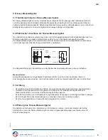
The bypass level indicator differential compensated forms an integral part of a pressure vessel. A chamber
is mounted on the side of a tank or container by means of two process connections. This direct connection
ensures that the level in the chamber corresponds precisely to the level of the liquid in the tank or container
( communicating pipes ). Inside the bypass chamber is a cylindrical float with a built-in magnetic system. The
concentrated magnetic field produced by the permanent magnet gives a precise reading for the level of liquid
in the chamber. By the magnetic field become actuated externally mounted display, recording and control
members.
The bypass level indicators differential compensated are used to monitor the fill level and to control liquids.
They are permitted to be integrated into containers and tanks that meet the technical requirements, i.e. that
are designed for the relevant operating parameters. The liquids must be free of or low in solids and not be
susceptible to gumming, conglomeration or crystallisation. The solid particles may not be magnetisable or, if
they are magnetisable, may not get close to the magnet.
The bypass level indicator differential compensated ( acc. to page 29 ) is bolted onto the side of the container
using a process flange ( 1 ) and a suitable seal ( 2) . The raised and flat faces as well as the gaskets have to
be mechanically perfectly matched. The correct gasket material has to be used for sealing according to the
medium, pressure and temperature.
If it is not attached at the factory of the BNA/BMG-....-DIF, please proceed as follows:
•
Remove the flange ( 4 ) / flange (
6 ) with seal.
• Insert wire cable ( 8
) without the float into the chamber
( 3 ) from topside.
• Fix the float (
9 ) with the ring at the bottom of the chamber onto the wire cable and pull upwards.
• At the other end of the wire cable fix the compensating weight (
10 ) onto the wire cable and insert the
compensating weight into the appropriate compensating tube ( 11 ).
• Put wire cable over the pulley ( 12 ).
•
Fit the top flange ( 4 ) with seal ( 5 ).
• Fit the bottom flange ( 6 ) with seal ( 7 ).
• Screw in the vent and drain plugs ( 13 ), if existing.
• the magnetic roller display ( 14 ) attach with two clamps on the chamber ( 3 ).
if existing
•
the magnetic float level transmitter
( 15 ) will be mounted onto the chamber or
magnetic roller indicator-profile.
• The magnetic switches ( 16
), depending on type, will be mounted onto the magnetic roller indicator-profile
or chamber at the required switching level.
2. Application area
3. Installation
1. Functional description
• Provisional installation may not be carried out if components or entire devices are faulty or incorrect, or if
components are missing
• Devices and their auxiliary devices may not be used as lifting gear, steps or handling devices
• If there are hazards, then safety signs, information, warning devices, suitable protective equipment or
isolators must be affixed according to directives and national regulations. If isolators are used, these must
be defined for the specific usage.
• Operating personnel must wear protective clothing in accordance with the local conditions and regulations.
Operating personnel must be trained, instructed and in possession of the technical documents.
• The operator is responsible for preventing unauthorised persons from accessing systems and devices,
and operating them.
• When devices and equipment are handed over to third parties, all documentation must also be supplied
together with these, in order to inform the third party of how to install, operate and use them
4. Hazard information
Heinrich Kübler AG
Ruessenstrasse 4 | CH-6340 Baar | T41 (0)41 766 62 62 | Fax +41 (0)41 766 62 63 | E-Mail [email protected] | Internet www.kubler.ch


