Operating instructions Nr. 114-4 GB
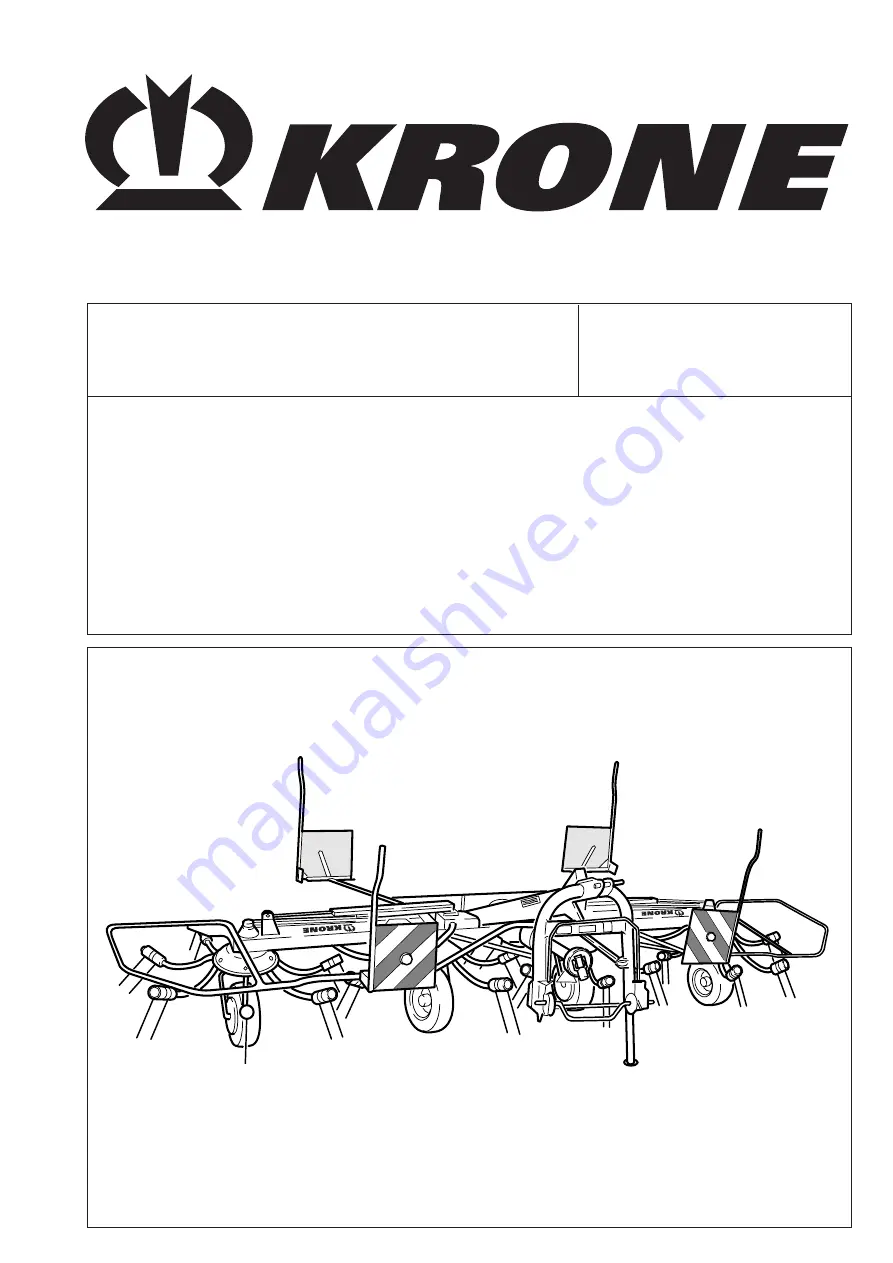
Rotary tedder
KW 5.50 / 4 x 7KW 6.70 / 6KW 7.70 / 6 x 7KW 8.80 / 8
(from machine no. 455 090)
Page 1: ...Operating instructions Nr 114 4 GB Rotary tedder KW 5 50 4 x 7 KW 6 70 6 KW 7 70 6 x 7 KW 8 80 8 from machine no 455 090 ...
Page 2: ...the other side We declare in our sole responsibility that the product to which this declaration refers corresponds to the relevant basic health and safety requirements of the EC directive 89 392 EEC 3 modification directive of 22 7 93 Spelle 01 09 99 Heinz Krone Business Director Dr Josef Horstmann Engineering Group Director Josef Jungehüser Director of Quality Control EC declaration of conformity...
Page 3: ...ns carefully before you use the machine and pay special attention to the safety instructions Important To avoid accidents and to ensure maximum results no alterations may be made to the machine without the manufacturer s permission Similarly the machine must only be used under the conditions prescribed by Krone All information illustrations and technical information in the operating instructions r...
Page 4: ...ort position 17 2 9 Disassembly of the rotary tedder 18 3 Settings 3 1 Special safety instructions 20 3 2 Spreading angle settings for the swather discs 20 3 3 Adapting the swather discs to the ground 21 3 4 Edge spreading mechanism 21 3 5 Stabilizers 22 3 6 Tine adjustment 23 4 Care and maintenance 4 1 Special safety instructions 24 4 2 General 24 4 3 Hydraulics 25 4 4 Gearbox 25 4 5 Tyres 25 4 6...
Page 5: ...more flexibility in steering and braking 20 When turning remember to take account of the wide load and or the greater weight of the equipment 21 Only switch on equipment when all protective devices are fitted and in protection position 2 Safety and Accident Prevention Regulations 1 Take note of both the regulations in these operating instructions and also the general safety and accident prevention...
Page 6: ...e to turn off the power take off shaft and the engine and remove the ignition key 5 When using P T O shafts with overload or free wheel clutches that are not covered by the guards on the tractor the overload or free wheel clutches must be fixed on the implement side 6 Always ensure correct assembly and guarding of the P T O shaft 7 Protect the P T O shaft guard from rotating with the shaft by fitt...
Page 7: ...raulic system make sure that all pressure has been released from the hydraulics of both the tractor and the implement 6 Maintenance 1 Repair maintenance and cleaning work and the correction of malfunctions must always be carried out only when the drive is turned off and the engine is at astandstill Removetheignitionkey Applytheparking brake 2 Nutsandboltsmustbecheckedregularlyfortightness and tigh...
Page 8: ...ned these danger notices in the form of so called warning symbols This chapter contains important information on the position of these warning labels and their meaning explanation Make sure that you are fully conversant with the meaning of the warning symbols opposite The text next to the symbols and the position of the signs on the machine give information about the specific danger points on the ...
Page 9: ...ing swather disk arms Maintain safe distance No personnel allowed inside swivel space of the operating equipment while the deployment arms are being folded down Accumulator is under gas and oil pressure Repairs can be carried out only in connection with replacement of the complete unit 6 Order No 942 196 1 2x Never reach into the danger zone between the three point frame and the carrier bar of the...
Page 10: ...8 KZW 1 001 1 2 Location of General Information Labels on the Machine 8 4 6 1 2 3 2 5 7 11 5 11 11 2 13 10 12 ...
Page 11: ...W 7 70 KW 8 80 924 573 0 1x KW 6 70 KW 7 70 KW 8 80 924 574 0 1x KW 6 70 KW 7 70 KW 8 80 13 Transport Service 939 172 3 440 135 3 1x bei KW 5 50 939 429 2 1x bei KW 6 70 440 148 2 1x bei KW 7 70 942 273 1 1x bei KW 8 80 942 295 0 500 lang 942 296 0 370 lang 942 297 0 200 lang grün 942 298 0 200 lang beige Traktor Steuerventil Schwimmstellung Vanne pilote du tracteur position flottante Tractor oper...
Page 12: ...ight kg 640 800 890 1100 Equivalent continuous sound pressure level under 70 d B A Tyres for all types 16 6 50 x 8 Tyre pressure 1 5 1 5 1 5 1 5 Three point mounting with quick Standard equipment coupler and run on mechanism Edge spreading mechanism hydr Standard equipment Spreading angle adjustment Standard equipment Additional tine loss protection Special accessory Plug in gearbox for night swat...
Page 13: ...or wheels are impossible Accident risk When raising and lowering the rotary tedder no persons may be allowed to go between the tractor and the rotary tedder High risk of injury When lowering the outer swather discs make sure that no persons are in the swivel area of the swather discs Accident risk Before you switch on the PTO shaft make sure that no persons are in the danger zone of the rotary ted...
Page 14: ...free running coupling facing the rotary tedder The disassembly of the PTO shaft protective sleeve is not necessary here Make sure that the locking device clicks into place Push the PTO shaft with the overload clutch onto the PTO shaft end on the rotary tedder Take care to ensure that the locking device 1 clicks into place Fit the protective sleeve again and secure it with a screw The withdrawal sp...
Page 15: ...draulics Make sure that the hydraulic system is depressureized in the tractor and in the rotary tedder attachment Transport locking device Push the PTO shaft onto the PTO shaft end of the tractor Make sure that the locking device clicks into place Fix the protective sleeve 1 with chains 2 to prevent it from rotating with the shaft Check the PTO shaft for correct length the first time the rotary te...
Page 16: ...nd and secure it in position 3 with a linch pin 1 Before raising the rear hydraulics make sure that the rear window of the tractor cabin is closed Otherwise the protective frame of the rotary tedder could cause damage KW 0 016 2 3 1 KW 0 053 2 1 3 KW 8 80 8 KW 4 001 1 The swather disk arms are secured in transport position with hydraulic stop valves on the hydraulic cylinders In cases of transport...
Page 17: ... them For the procedure for measuring and shortening the shaft please refer to the operating manual of the PTO shaft manufacturer 2 4 Adjusting the PTO shaft length All types of rotary tedder are equipped with the standard brackets 2 for lighting systems on the warning signs 1 White limiting lights must be fitted to the brackets on the front warning signs Three unit lamps must be fitted on the rea...
Page 18: ...lt 1 and linch pin NOTE Observe the position of the individual wheels when lowering into working position see chapter Adjusting the swather disk spreading angle 2 6 Converting from transport to working position When the outer swather discs are being lowered no persons may be allowed to enter the swivel area of the outer swather discs KWT 0 014 2 1 KW 0 012 1 2 KW 4 001 1 Select the position Lower ...
Page 19: ...nd KW 7 70 6x7 Raise the outer swather discs until the locking devices 1 have fully clicked into place Before raising the rear hydraulics check that the rear window of the tractor cabin is closed Otherwise the protective frame could cause damage KW 0 049 2 1 b a KW 0 051 1 KW 4 001 1 Attach the lighting system Check that the lights work KW 8 80 8 Lift outer swather disks until the cylinders have t...
Page 20: ...wn the front jack stand 1 from position 3 and secure with a linch pin 2 Jack stand at front Fold down the rear jack stand 2 from position 3 and secure it with a linch pin 1 For reducing the transport width 3 m Lower the undercarriage wheel 3 on the second wather disk backwards into transport position Secure with the bolt 1 and the linch pin 2 CAUTION Observe the maximum width of the machine when t...
Page 21: ...x7 KW 6 70 6 and KW 7 70 6x7 two hydraulic hoses for KW 8 80 8 Take the hydraulic switchover valve 1 from the bracket on the tractor and place it in the corresponding bracket 4 on the rotary tedder Insert the coupling of the hydraulic hose into the bracket 3 on the three point frame Disconnect the control cable for kW 5 50 4x KW 6 70 6 and KW 7 70 6x7 and the electrical lighting cable from the tra...
Page 22: ... the rear hydraulic system take steps to prevent it from being accidentally lowered Settings Remove the linch pin 1 and pull out the pin 2 Move the wheel bracket 3 to the selected position between position I and position II Insert the pin again and secure it with the linch pin Pin towards position I steeper spreading angle Pin towards position II flatter spreading angle Flat spreading angle II I l...
Page 23: ...htly The stop 3 must not rest on the adjusting screw 2 Undo the counter nut 1 Turn the adjusting screw until in the required position a at least 41 mm Tighten the counter nut again after adujstment KW 4 004 1 a KWT 0 040 1 2 a 3 4 Wide spreading tedding 3 3 Drive rpms Take the mowing swaths as much as possible between the swather disks In cases of heavy fodder move with high rpm 540 min and a not ...
Page 24: ... or the stabilizers may lock 3 5 Edge spreading mechanism To adjust the edge spreading mechanism raise the rotary tredder Switch the hydraulic switchover valve 1 to position b edge spreading mechanism The edge spreading mechanism can be adjusted from the control valve on the tractor The setting of the undercarriage wheels can be seen on the pointer The undercarriage wheel setting can be seen on th...
Page 25: ...d vertically to the ground The alignment of the tines can be changed by turning the eccentric For adjustment release securing bolt 1 and turn eccentric 2 to the next position Tighten the adjustment screw to a torque setting of 95 Nm KW 1 058 1 3 90 2 ...
Page 26: ...r the cleaning greasing and oiling of parts and components and the inspection and tightening of bolts The bolts on all tines must be checked after the first hours of operation and tightened if necessary 95 Nm and thereafter checked daily and tightened if necessary After each extended period of non operation ventilate the friction coupling on the PTO shaft KW 7 70 KW 8 80 4 2 General Independently ...
Page 27: ...e the ignition key Place the rotary tedder on a firm level surface Fit wheel blocks to protect it from accidental rolling Check the air pressure regularly 4 5 Tyres The PTO shaft s on the machine should be greased at the points shown in the illustration at the time intervals shown At the same time observe the operating instructions of the PTO shaft manufacturer PTO shaft 4 6 Lubrication points on ...
Page 28: ...26 Lubrication points on the KW 5 50 4x7 KW 0 061 1 50h 11 50h 6 50h 12 10h 15 50 h 7 50h 10h 10h ...
Page 29: ...27 Lubrication points on the KW 6 70 6 and KW 7 70 6x7 KW 4 062 15 50 h 1 50h 12 10h 7 50h 10h 13 11 50h 50h 6 10h 10 h ...
Page 30: ... For reasons of clarity the lubrication points have been shown on only one side of the rotary tedder On the other side there are lubrication nipples at exactly the same points as a mirror image 50h 50h 50h 50h KW 4 002 50h 10h 10h 10 h 10h ...
Page 31: ...l the PTO shaft apart Lubricate the inner tubes and the protective tubes with grease Grease the lubrication nipples on the universal joint and the bearing rings of the protective tubes Store the rotary tedder in a dry place and not near artificial fertilizers or stables Touch up paintwork Bare metal must be thoroughly preserved with anti corrosion agent To lift the tyres the tyres can be damaged i...
Page 32: ...om the rotary tedder drive cf chapter 2 2 Preparations on the tractor and rotary tedder Fit the protecting pot 3 and fix with the clamp fitting 4 On the KW 7 70 and KW 8 80 the existing PTO shaft guard must be dismantled Fix the angled bracket 2 to the designed holes with bolts 5 and nuts on the left and right side of the carrier bar On the KW 5 50 fit the angled brackets in such a way that the sh...
Page 33: ...y Protect the tractor and rotary tedder from rolling 7 2 Additional tine loss safety mechanism It is essential to place a protective cover on the free PTO stup shaft Apart from the standard tine loss safety mechanism 5 it is possible to fit an additional tine securing mechanism Per tine it consists of one cable two cable clamps each with two flat round washers and safety washers Fit the cable 4 wi...
Page 34: ...e wheel bracket Then remove the anti winding pot Push the anti winding disc onto the wheel bracket Assemble the wheel in the opposite order A wheel guard is available for the middle wheels The wheel guard kit consists of Wheel cover 4 with screw on clip 2 and distance plate 3 Two M 10 hexagonal bolts with spring washers 1 M 8 clamp screw with washer and nut 5 Anti winding disc 6 Guard extension 7 ...
Page 35: ...l bracket 4 The bolt 3 must lie on the wheel bracket Mount the distance plate 5 between the wheel bracket and the wheel guard Put the screw on clip 6 in place and screw it tight After assembly has been completed check whether the wheel 2 rubs against the wheel guard If necessary align the wheel guard KW 0 023 3 1 4 5 6 2 KW 0 025 4 1 2 3 After wheel guard has been mounted remount the undercarriage...
Page 36: ...the carrier bar with cable ties at the holes 3 provided The illustration shows the carrier bar as seen from below A permanently fixed lighting system can be mounted on all rotary tedders To fit the system unscrew the brack ets for fitting the removeable lights on the warning signs 1 In the middle of the square warning signs and at the lower end of the oblong warning signs there is a hole 3 through...
Page 37: ...0 6 KW 7 70 6x7 and KW 8 80 8 The work described on the following pages must only be carried out by authorized specialist dealers Because safety devices must be mounted as well the rotary tedder cannot be put into operation until all the tasks described below have been completely carried out ...
Page 38: ...e the rotary tedder to working position 3 Mounting the wheels For reasons of transport some undercarriage wheels are not mounted They must be so mounted that for discs that rotate anti clockwise beige tines the wheel bracket is to the right of the wheel For discs that rotate clockwise green tines the wheel bracket must be to the left of the wheel in Fahrtrichtung gesehen 4 Mounting the disc arms t...
Page 39: ...unt them on each end with 4 M10 bolts Tighten the bolts 2 on the left and right stabilizer 1 until the stabilizer is fixed Remove the roll pin 4 and knock out the bolt 3 Front protective frames on the left and right 5 1 Mounting the protective frames to the KW 5 50 4x7 5 Mounting the protective frames Release the bolt 2 on the left and right side of the machine and detach the transport bracket 1 K...
Page 40: ...the stabilizer 1 to the holding bracket 4 of the protective frame with bolts 3 and secure it with a roll pin Re lease the adjustment bolts 2 on the stablizer again Rear protective frame Fix the rear protective frame 1 to the carrier bar with bolts 3 For connecting of the rear protective frames to together use bolts 2 at the support foot 4 KW 0 043 1 2 3 KW 0 044 3 4 2 1 KW 0 045 1 3 3 2 4 ...
Page 41: ... KW 6 70 6 and KW 7 70 6x7 Protective frames a and b are mounted in the factory Mounting of the protective frames c front protective frames and d rear protective frames is carried out as described for the KW 5 50 4x7 see 5 1 KW 4 003 d c a b ...
Page 42: ...rames to the KW 8 80 8 d c a b KW 4 005 Protective frames a and b are mounted in the factory Mounting of the protective frames c front protective frames and d rear protective frames is carried out as described for the KW 5 50 4x7 see 5 1 ...
Page 43: ...d right through 5 4 Mounting the warning signs The illustration shows the mounting positions of the front light brackets 1 and 4 and the rear light brackets 2 and 3 on the warning signs The lights can only be inserted when the brackets have been mounted Light brackets for removeable lights KW 5 50 4x7 KW 0 066 3 2 1 4 KW 0 065 1 2 3 1 2 3 ...
Page 44: ...7 7 4 5 6 5 2 3 1 5 5 6 6 5 6 5 6 5 6 5 5 1 4 5 5 2 3 995 lg 700 lg 1 M 10 x 25 6 Anzahl Pos Maße 3 M 10 x 55 2 M 10 x 45 8 4 5 10 5 x 21 x 2 4 10 5 x 25 x 4 36 4 6 NM 10 18 Anzahl Pos Maße 9 M 8 8 7 M 8 x 20 8 8 8 4 x 17 x 4 16 Always mount the warning signs so that the stripes are pointing downwards and showing outwards ...
Page 45: ...43 ...
Page 46: ...ernard Krone GmbH Heinrich Krone Straße 10 D 48480 Spelle Postfach 11 63 D 48478 Spelle Phone 049 0 59 77 935 0 Fax 049 0 59 77 935 339 Internet http www krone de eMail info ldm krone de konsequent kompetent 19 Jun 2007 ...