6
1.2
Mass Flow Sensor
1.2.1 Measuring Principle
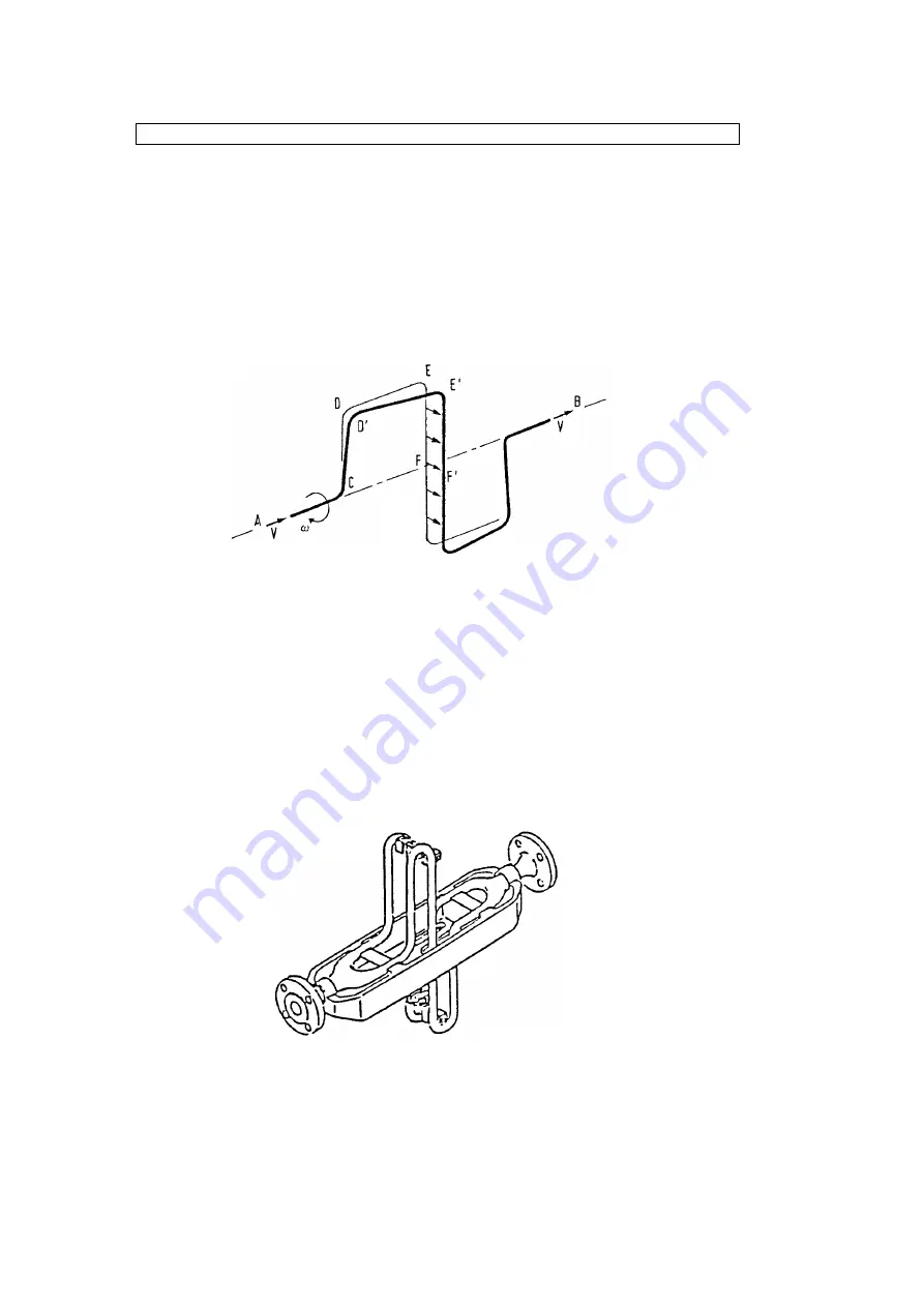
Coriolis forces occur in rotating systems when accompanying bodies are moved toward or
away from the rotational axis. This is illustrated by the following simple set-up: a pipe tube
rotates with a constant angular velocity around the axis A - B (figure 2). The fluid particles
flow with the velocity v through the loop. Between the points C and D they move away from
the axis and therefore have to be accelerated from a smaller to a larger tangential velocity.
Respectively, the fluid particles have to decelerate reducing their tangential velocity between
points E and F. The opposing coriolis forces acting upon the two different parts of the pipe
loop are directly proportional to the product of the mass and the velocity of the fluid. They
cause the pipe loop to deform (DD’, EE’ and FF’ respectively) with respect to a rotating loop
filled with a flowing fluid.
Fig. 2 Coriolis force in a rotating pipe loop
Rotation does not necessarily mean the completion of full circular orbits. Short circular
segments suffice. In the event of oscillation, the deformation of the pipe loop sides oscillates,
too. The total change in the motion of the pipe loop caused by the mass flow can be detected
via inductive sensors. A signal directly related the mass flow rate of the fluid flowing through
the pipe loop is then generated after appropriate signal processing.
1.2.2 Transducer MFS 2000 (P-Series)
For greater sized mass flow meters it has proven to be of advantage for the fluid to flow
through two parallel measuring loops, which oscillate in opposite directions and with a phase
difference of 180°. This symmetrical arrangement of the loops and the stiffness of the bridge
(i.e. the pipe loop supports) suppress most disturbances caused by external equipment.
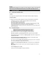
Figure 3 displays an optimised transducer of the MFS 2000 series designed for mass flow
measurement.
Fig. 3: Transducer MFS 2000 without housing


