9
2.
HARDWARE
2.1
Connectors
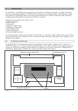
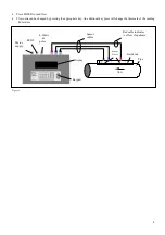
There are six connectors on the electronic housing, three of which are directly connected to the transducer assemblies and three
are for the output facilities.
NOTE: To remove the cable connectors from the sensor blocks, fully retract each block into the guide rail by turning the
knurled knob clockwise. DO NOT pull on the cables.
RS 232 CONNECTORS
9 way “D” plug viewed from reverse
5-pin plug viewed from reverse
4 - 20mA and Pulse Cable
Connections
4 - 20mA - Red positive,
Black negative.
Pulse - White positive,
Green negative.
9v DC in
1A Max
RS232
Pulse
4-20 mA
-
+
red
blue
black
Figure 5
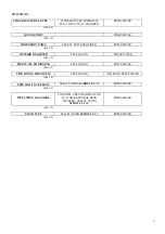
Pin 3 RS232 RXD white
Pin 4 RS232 DTR black
Pin 5 GND screen
Pin 2 RS232 TXD green
Pin 6 RS232 DSR red
Pin 5 RS232 RXD white
Pin 4 RS232 TXD green
Pin 1 (marked) RS232 DSR red
Pin 2 RS232 DTR black
Pin 3 GND screen

