background image

Connecting a VS-21HDCP-IR 2x1 DVI Switcher 


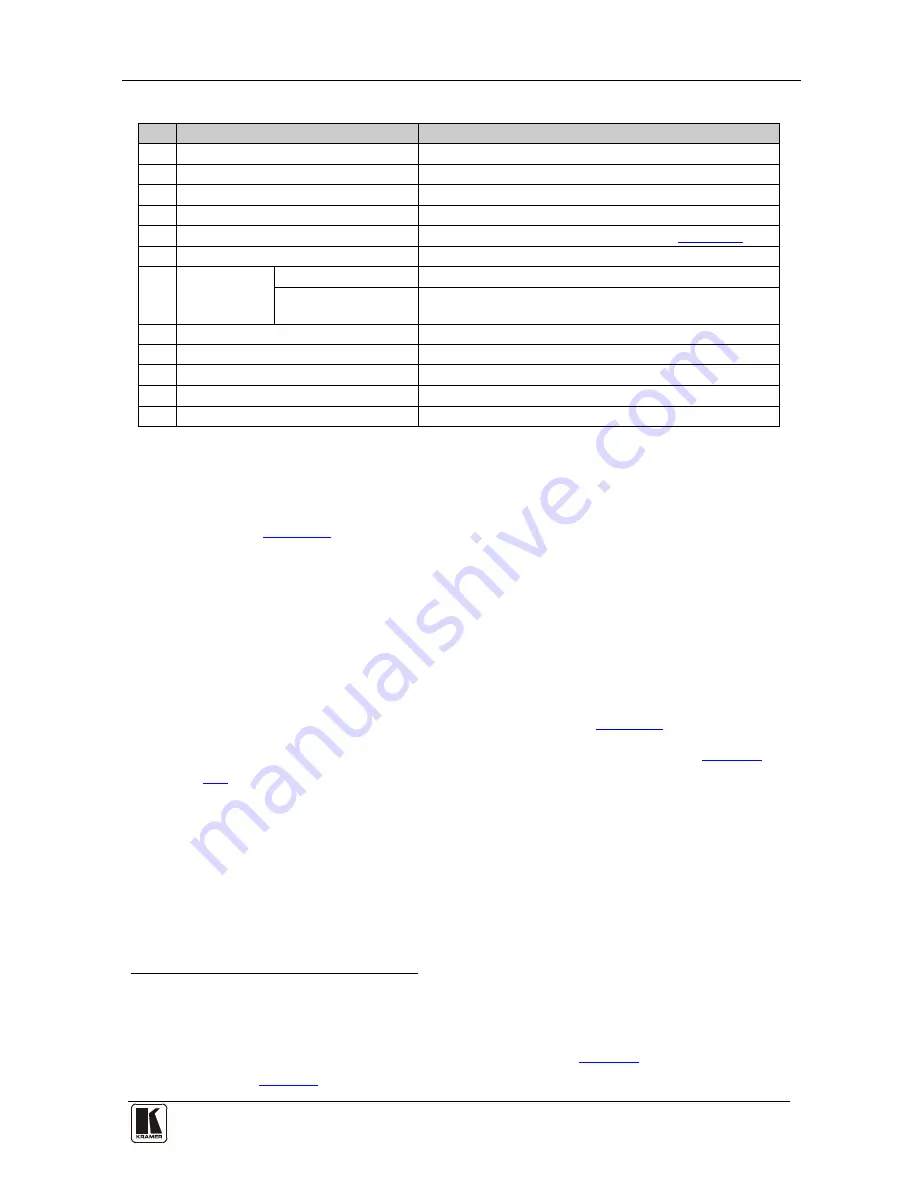
Table 1: VS-21HDCP-IR 2x1 DVI Switcher Features 

Feature 

Function 

INPUT


DVI Connector 

Connect to the DVI source 1 

INPUT 2 

DVI Connector 

Connect to the DVI source 2 

OUTPUT 

DVI Connector


Connect to the DVI acceptor 

RS-232

 9-pin D-sub Connector 

Connects to the PC or Serial Controller

1


REMOTE 

Terminal Block Connectors  Connect to a contact closure switch (see 

Section  5.3

5V DC 

+5V DC connector for powering the unit 

REMOTE IR  

Receiver


Window


Receives signals from the infrared remote control transmitter 


LED


(yellow)


The yellow LED lights when receiving signals from the 

infrared remote control transmitter 

ON 

LED (Green

Lights when receiving power 

IN 1 

LED (Green)


Lights when input 1


is selected 

10 

IN 2 

LED (Green) 

Lights when input 

is selected 

11 

OUT

 LED (Green) 

Lights when the output is connected 

12 

SELECT

 Switch


Press to toggle between selecting input 1 and input 2 

5  Connecting a VS-21HDCP-IR 2x1 DVI Switcher 

To connect the 

VS-21HDCP-IR


2x1 DVI Switcher

, as illustrated in the 

example in 

Figure 2

, do the following

2

1.  Connect up to two DVI sources to the INPUT connectors, as follows: 


INPUT 1 connector to DVI source 1 (for example, a computer) 


INPUT 2 connector to DVI source 2 (for example, a set top box) 

2.  Connect the OUTPUT connector to the DVI acceptor (for example, a 

DVI display). 

3.  Connect the 5V DC power adapter to the power socket and connect the 

adapter to the mains electricity (not illustrated in 

Figure 2

). 

4.  If required, connect a PC or controller to the RS-232 port (see 

Section 

 5.1

5.  Press the SELECT button

). 

3


1 No Null-modem adapter/Connector is required 

 to choose which DVI input to route to the 

output.  

The SELECT button toggles between INPUT 1


and INPUT 2, lighting 

the IN 1 LED when INPUT 1 is selected, or the IN 2


LED when IN 2 is 

selected. 

2  Switch OFF the power on each device before connecting  it to your VS-21HDCP-IR. After connecting your  
VS-21HDCP-IR, switch on its power and then switch on the power on each device 
3 Alternatively you can press key 1 or 2 on the remote transmitter, once setup (see 

Section  5.2

), or use the contact closure 

remote control pins (see 

Section  5.3

) or use RS-232 

Summary of Contents for VS-21HDCP-IR

Page 1: ...Kramer Electronics Ltd USER MANUAL Model VS 21HDCP IR 2x1 DVI Switcher...

Page 2: ...ng EDID 8 7 Technical Specifications 8 8 Default Communication Parameters 9 9 Kramer Protocol 9 9 1 Toggling Between Protocols 9 9 2 Kramer Protocol 2000 10 9 3 Protocol 3000 Syntax 11 9 3 1 Host Mess...

Page 3: ...IR 2x1 DVI Switcher 6 Figure 3 Connecting the REMOTE Input Select Connector 7 Tables Table 1 VS 21HDCP IR 2x1 DVI Switcher Features 5 Table 2 Technical Specifications of the VS 21HDCP IR 2x1 DVI Switc...

Page 4: ...g the required battery and a separate user manual2 This user manual 2 Bracket installation kit 2 Getting Started We recommend that you Unpack the equipment carefully and save the original box and pack...

Page 5: ...KRAMER SIMPLE CREATIVE TECHNOLOGY Getting Started 2...

Page 6: ...gital video and audio signals transmitted over DVI or HDMI connections between two HDCP enabled devices to eliminate the reproduction of copyrighted material To protect copyright holders such as movie...

Page 7: ...oiding interference deterioration in signal quality due to poor matching and elevated noise levels often associated with low quality cables Avoiding interference from neighboring electrical appliances...

Page 8: ...ect the VS 21HDCP IR 2x1 DVI Switcher as illustrated in the example in Figure 2 do the following2 1 Connect up to two DVI sources to the INPUT connectors as follows INPUT 1 connector to DVI source 1 f...

Page 9: ...ct to the VS 21HDCP IR via an RS 232 connection using for example a PC Note that a null modem adapter connection is not required To connect to the VS 21HDCP IR via RS 232 Connect the RS 232 9 pin D su...

Page 10: ...e REMOTE Terminal Block Connector The contact closure remote control pins operate in a similar way to the input SELECT button Using the contact closure remote control lets you select an input by remot...

Page 11: ...put 1 and input 2 simultaneously IN 1 IN 2 blink Default value to Input 1 and input 2 simultaneously 7 Technical Specifications Table 2 includes the technical specifications Table 2 Technical Specific...

Page 12: ...n release 9 Kramer Protocol By default the VS 21HDCP IR is set to protocol2 2000 see section 9 2 but is also compatible with Kramer s Protocol 3000 see section 9 3 Section 9 1 describes how to switch...

Page 13: ...s 1 I6 I0 INPUT When switching ie instruction codes 1 and 2 the INPUT 7 bits is set as the input number which is to be switched Similarly if switching is done via the machine s front panel then these...

Page 14: ...cause all units including audio data etc to switch Similarly if a machine is in FOLLOW mode it will perform any video instruction 9 3 Protocol 3000 Syntax The Kramer Protocol 3000 lets you control th...

Page 15: ...ommand entered as part of a message string begins with a message starting character and ends with a message closing character Note A string can contain more than one command Commands are separated by...

Page 16: ...can be chained in the same string Each command is delimited by a pipe character When chaining commands enter the message starting character and the message closing character only once at the beginnin...

Page 17: ...ULT VID V Switch video only VID IN OUT IN OUT Short form V IN OUT IN OUT VID IN OUT IN OUT RESULT VID V Query Switch video only VID OUT Short form V OUT VID VID IN OUT VID IN 1 IN 2 9 1 Result and Err...

Page 18: ...fnature ii Product modification orfailureto followinstructions supplied with theproduct iii Repairorattemptedrepairby anyonenot authorized byKramer iv Anyshipment oftheproduct claims must bepresentedt...

Page 19: ...est information on our products and a list of Kramer distributors visit our Web site www kramerelectronics com where updates to this user manual may be found We welcome your questions comments and fee...

Reviews: