background image

KRAMER:  SIMPLE CREATIVE TECHNOLOGY


Operating the VP-423 PC Video-Wall Scaler 


6.2.2  The MAIN MENU 

Table 2

 defines the main menu parameters and functions: 

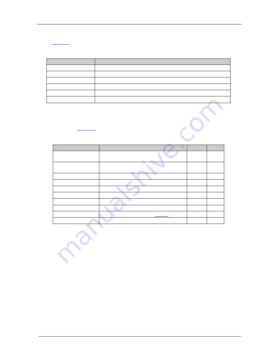
Table 2: The Main Menu Parameters and Functions 

Parameter 

Function 

WALL ARRANGEMENT  Sets the wall arrangement 

COLOR 

Adjusts the color, brightness and contrast settings of the display 

FINETUNE 

Fine tunes the position of the display and the timing parameters 

FACTORY RESET 

Resets the device to its factory default parameters  

INFORMATION 

Displays the source, input and output resolutions and the software version 

EXIT 

Select to exit the OSD 

6.2.3  The WALL ARRANGEMENT Submenu 

The WALL ARRANGEMENT menu defines the wall arrangement setup, as 
defined in 

Table 3

Table 3: The WALL ARRANGEMENT Menu Parameters and Functions 

Parameter 

Function 

Range   Default 

DISP. WIDTH 

Set the number of screens comprising the width 

of the wall display 

1 to 4 

DISP. HEIGHT 

Set the number of screens comprising the 

height of the wall display  

1 to 4 

DISP. POS X 

Set the X position of the display in the matrix 

1 to 4 

DISP. POS Y 

Set the Y position of the display in the matrix 

1 to 4 

LEFT FINETUNE 

Move the picture on the screen to the left  

0 to 255 

RIGHT FINETUNE 

Move the picture on the screen to the right 

0 to 255 

TOP FINETUNE 

Move the picture on the screen up 

0 to 255 

BOTTOM FINETUNE 

Move the picture on the screen down 

0 to 255 

OUTPUT 

Sets the output resolution (see 

Table 4


EXIT 

Select to exit the OSD 


Summary of Contents for VP-423

Page 1: ...Kramer Electronics Ltd USER MANUAL Model VP 423 PC Video Wall Scaler...

Page 2: ...Arrangement 10 8 Technical Specifications 12 Figures Figure 1 VP 423 PC Video Wall Scaler Front and Rear View 4 Figure 2 Connecting the VP 423 PC Video Wall Scaler 6 Figure 3 Setting the X and Y Posi...

Page 3: ...er Power adapter 5V DC input This user manual2 2 Getting Started We recommend that you Unpack the equipment carefully and save the original box and packaging materials for possible future shipment Rev...

Page 4: ...KRAMER SIMPLE CREATIVE TECHNOLOGY Getting Started 2...

Page 5: ...p for convenient signal adjustment A non volatile memory that retains the last settings used Quick auto adjust via the OSD Operation directly via the front panel push buttons and the on screen display...

Page 6: ...ctor is not used release to Hi Z when an additional unit is connected to the PC LOOP connector 4 PC INPUT 15 pin HD connector Connect to a computer graphics source 5 5V DC 5V DC connector for powering...

Page 7: ...HD connector to the PC INPUT 15 pin HD connector of the next VP 423 unit unit 2 2 On the second unit Connect the PC OUTPUT 15 pin HD connector to a display Release the TERM button to the Hi Z position...

Page 8: ...The VP 423 is operated directly via the front panel buttons see Section 6 1 and via the OSD menu see Section 6 2 6 1 Using the Front Panel Buttons During normal operation no OSD is shown pressing the...

Page 9: ...essing ENTER selects and activates a menu item or accepts the parameter value set Pressing MENU closes the OSD menu1 As an example of how to set the parameters such as to increase the contrast on the...

Page 10: ...u The WALL ARRANGEMENT menu defines the wall arrangement setup as defined in Table 3 Table 3 The WALL ARRANGEMENT Menu Parameters and Functions Parameter Function Range Default DISP WIDTH Set the numb...

Page 11: ...display via the OUTPUT item in the WALL ARRANGEMENT menu Each press of the or button cycles through the list of resolutions Table 4 defines the available output resolutions and how they appear in the...

Page 12: ...sition of the display 0 to 254 127 CLOCK1 Adjust the clock frequency 0 to 254 127 PHASE1 Adjust the clock phase 0 to 63 0 AUTO ADJUST Automatically adjusts the above parameters EXIT Exit this menu 7 S...

Page 13: ...to 2 and press ENTER 7 Set the position of each display2 Figure 4 on the TV wall via the DISP POS X and the DISP POS Y sub menus for each screen as defined in Figure 4 Setting the Position of Each Dis...

Page 14: ...olution perform the setup procedure once again 8 Technical Specifications Table 7 lists the technical specifications Table 7 Technical Specifications 1 INPUT of the VP 423 PC Video Wall Scaler 1 PC lo...

Page 15: ...heractsofnature ii Product modification orfailureto followinstructions supplied with theproduct iii Repairorattemptedrepairby anyonenot authorized byKramer iv Anyshipment oftheproduct claims must bepr...

Page 16: ...or the latest information on our products and a list of Kramer distributors visit our Web site www kramerelectronics com where updates to this user manual may be found We welcome your questions commen...

Reviews: