


KRAMER: SIMPLE CREATIVE TECHNOLOGY
Setting the Wall Arrangement
10
6.3
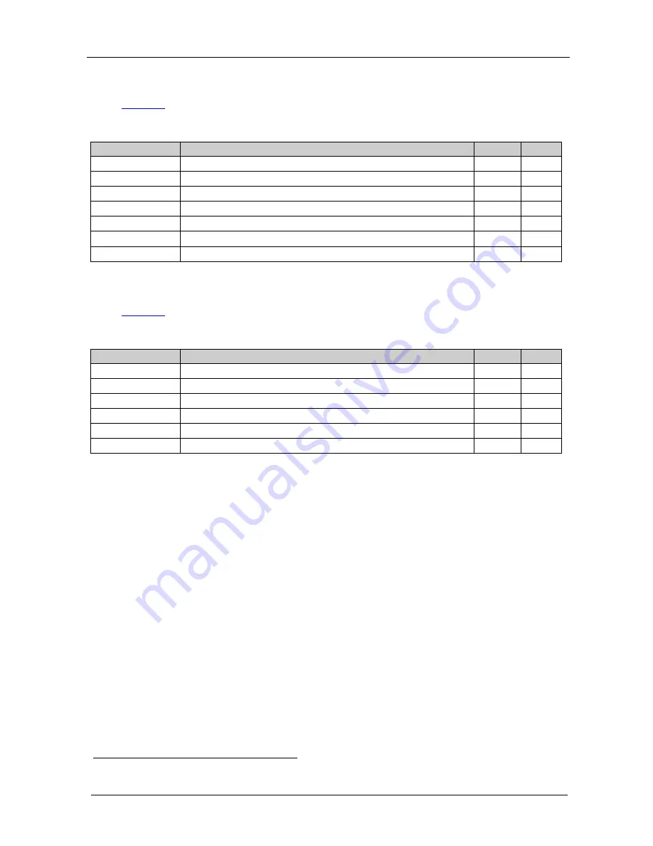
The COLOR Submenu
Table 5
defines the COLOR menu:
Table 5: The COLOR Menu – Available Adjustments
Parameter
Function
Range Default
CONTRAST
Adjust the contrast
0 to 255
105
BRIGHTNESS
Adjust the brightness
0 to 192
96
R
Adjust the red component
0 to 255
128
G
Adjust the green component
0 to 255
128
B
Adjust the blue component
0 to 255
128
AUTOCOLOR
Set the color automatically
EXIT
Exit this menu
6.4
The FINETUNE Submenu
Table 6
defines the FINETUNE menu:
Table 6: The FINETUNE Submenu
Parameter
Function
Range Default
H-POSITION
Set the horizontal position of the display
0 to 254
127
V-POSITION
Set the vertical position of the display
0 to 254
127
CLOCK
1
Adjust the clock frequency
0 to 254
127
PHASE
1
Adjust the clock phase
0 to 63
0
AUTO ADJUST
Automatically adjusts the above parameters
EXIT
Exit this menu
7
Setting the Wall Arrangement
To set the wall arrangement, do the following:
1. Set the input resolution from the PC to the highest possible resolution.
2. Press the MENU front panel button to activate the OSD, and select the
WALL ARRANGEMENT submenu.
3. Select OUTPUT and select the display's native resolution (for example,
1920x1200
)
.
Be sure to set the resolution on all the scalers to the same value.
4. Set each scaler to input a full screen picture:
Press the MENU button
Select WALL ARRANGEMENT
Select DISPLAY WIDTH and set to 1
Press the ENTER button
Select DISPLAY HEIGHT and set to 1
1 We recommend adjustment via the auto adjust function rather than manually adjusting the clock and phase


