67
66
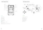
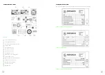
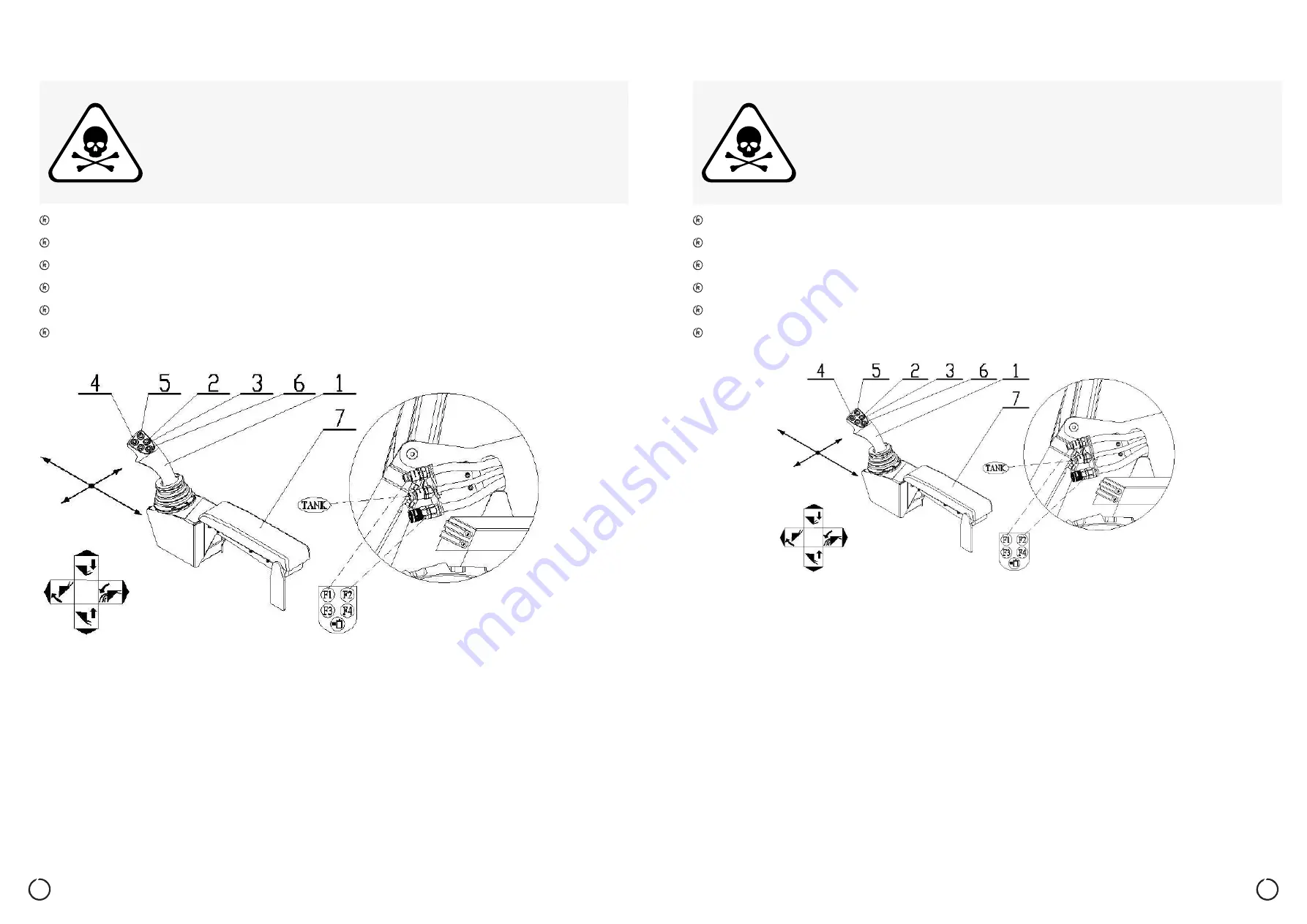
Lowering the boom - push the control lever (1) forward.
Raising the boom - pull the control lever (1) backwards.
Tilting the bucket shut - push the control lever (1) left.
Tilting the bucket open - push the control lever (1) right.
Lowering the boom while at the same time tilting the bucket shut - push the control lever (1) forward and left.
Lowering the boom while at the same time tilting the bucket open - push the control lever (1) forward and right.
Raising the boom while at the same time tilting the bucket open - pull the control lever (1) backwards and right.
Raising the boom while at the same time tilting the bucket shut - pull the control lever (1) backwards and left.
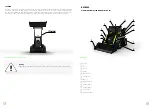
12. LOADER CONTROL WITH THE WORK ADD-ON (BOOM WITH BUCKET)
Tighten the seat belt well.
The safety ramp must be lowered.
Keep your feet on the footrests and your hands on the control levers.
Make sure there is no other person or living creature in the travel area.
The windows must be clean for a good view.
Adjust the rear-vision mirrors correctly for a good view to the rear.
Danger
Risk of serious or fatal injuries when operating the loader!
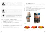
Picture 55
13. LOADER CONTROL WITH AUXILIARY HYDRAULIC DEVICE
Tighten the seat belt well.
The safety ramp must be lowered.
Keep your feet on the footrests and your hands on the control levers.
Make sure there is no other person or living creature in the travel area.
The windows must be clean for a good view.
Adjust the rear-vision mirrors correctly for a good view to the rear.
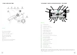
Some attachments require in order to function a connection to a hydraulic power and flow source. The connection to the
loader is through quick couplings, which are located on the left arm of the boom. These are marked as F1, F2, TANK.
Before connecting an attachment, check the technical condition and technical specifications.
Always wear protective gloves and goggles when connecting and disconnecting, as the hydraulic oil and quick couplings
may be as hot as 90 °C - risk of burns.
Do not connect damaged or technically incompatible attachments as they may cause serious damage to the loader and
other property, or pose a Danger to life.
Clean the quick couplings after use and put on the protective covers.
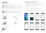
An attachment is operated with buttons (4) and (5) on the left control lever (1). The hydraulic flow lock is activated by button
(3) on the left control lever (1). When the hydraulic flow lock is activated, the indicator (17) in the control application lights up
in yellow. You can change the hydraulic flow volume (between 20 and 65 l) in the application by a combination of touch
buttons (17) and (5) as follows: press the touch button (17). The touch key starts flashing until a selection is made with button
(5). The selected request (6) remains lit in blue. The hydraulic oil flow rate is divided equivalently to the vehicle travel speed
into 4 levels, which are: Level 1 = 20 l, level 2 = 30 l, level 3 = 45 l, and level 4 = 65 l.
Danger
Risk of serious or fatal injuries when operating the loader and its attachments!
Picture 56

