AM4011
Power Considerations
ID 1022-1626, Rev. 1.0
Page 5 - 3
P R E L I M I N A R Y
5.
Power Considerations
5.1
AM4011 Voltage Ranges
The AM4011 board has been designed for optimal power input and distribution. Still it is nec-
essary to observe certain criteria essential for application stability and reliability.
The AM4011 requires two power sources, the module management power for the MMC (nom-
inal: 3.3V DC) and a single payload power (nominal: 12V DC) for the module components.
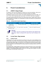
The following table specifies the ranges for the different input power voltages within which the
board is functional. The AM4011 is not guaranteed to function if the board is not operated within
the operating range.
5.2
Carrier Power Requirements
5.2.1
Payload Power
Payload power is the power provided to the module from the carrier or the backplane for the
main function of the module. The payload power voltage should be selected at the higher end
of the specified voltage range. The continuous current limit value is based on the power limit of
60 W per module at the minimum supply value. The maximum current value for the payload
power is derived from a 25% derating of the connector pins, which allow a total of 6.0 A (0.75 A
per pin; 8 pins).
The payload power voltage shall be at least 10.8 V and not more than 13.2 V at the module
contacts during normal conditions under all loads (see Table 5-1, “DC Operational Input Voltage
Ranges”). The bandwidth-limited periodic noise due to switching power supplies or any other
source shall not exceed 200 mV peak to peak.
Table 5-1:
DC Operational Input Voltage Ranges
INPUT SUPPLY VOLTAGE
ABSOLUTE RANGE
OPERATING RANGE
Payload Power
(nominal: 12V DC)
10.0 V min. to 14.0 V max.
10.8 V min. to 13.2 V max.
Module Management Power
(nominal: 3.3V DC)
2.97 V min. to 3.63 V. max. (±10%)
3.135 V min. to 3.465 V max. (±5%)
Warning!
The AM4011 must not be operated beyond the absolute range indicated in the
table above. Failure to comply with the above may result in damage to the
board.


