AM4011
Introduction
ID 1022-1626, Rev. 1.0
Page 1 - 11
P R E L I M I N A R Y
Onboard
Con
tro
ller
Gigabit Ethernet
Two Intel® 82571EB Dual Gigabit Ethernet PCI Express bus controllers:
•
One controller connected to the Common Options Region
•
One controller connected to Front I/O
AMC Interconnection
Gigabit Ethernet
Common Options Region ports 0-1
•
Two Gigabit Ethernet SerDes ports
Serial ATA
Common Options Region ports 2-3
•
Two Serial ATA 150 ports
PCI Express
Fat Pipes Region ports 4-7
•
One x4 PCI Express interface operating as a root complex controller only
Debug Interface
Extended Options Region port 14
•
One Debug port
Serial Interface
Extended Options Region port 15
•
One Serial port
Clock Input
Clocks
•
PCI Express clock reference input (FCLKA)
Connectors
Front Panel
Connectors
•
One USB 2.0 port on a 5-pin, mini USB type A connector
•
One Serial port (COM1) with RS-232 signal level on a mini 10-pin con-
nector
•
Two Gigabit Ethernet ports on two RJ-45 connectors
Onboard Connector
•
One USB 2.0 connector for optional NAND Flash
AMC Card-edge
Connector
•
One 170-pin AMC Card-edge connector
Switch
DIP Switch
One DIP switch consisting of four switches for board configuration
LEDs
Module Management
LEDs
•
LED1 (red):
Out-of-Service LED
•
LED2 (red/green/amber):
Health LED
•
HS LED (blue):
The hot swap indicator provides basic feed-
back to the user on the hot swap state of the
module. The HS LED states are
off
,
short
blink
,
long blink
, and
on
.
User-Specific LEDs
•
ULED3 (red/green):
AMC Eth. port A link signal status or BIOS
POST code LED
•
ULED2 (red/green):
Front Eth. port C link signal status or BIOS
POST code LED
•
ULED1 (red/green):
Front Eth. port D link signal status or BIOS
POST code LED
•
ULED0 (red/green):
AMC Eth. port B link signal status or BIOS
POST code LED
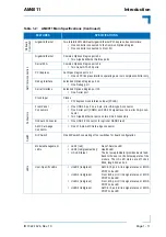
Table 1-2:
AM4011 Main Specifications (Continued)
FEATURES
SPECIFICATIONS


