Functional Description
AM4011
Page 2 - 18
ID 1022-1626, Rev. 1.0
P R E L I M I N A R Y
2.4.2
Synchronization Clock Interface
On the AM4011, two PCI Express reference clock configurations are supported in accordance
with the PCI Express Base Specification Revision 1.0a. One configuration uses two separate
100 MHz reference clocks, one on the AM4011 and one on the carrier. The other configuration
uses one common clock source for both the AM4011 and the carrier. If the common clock
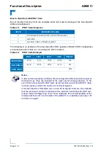
source is used, the AM4011 uses the AMC clock interface FCLKA (see Figure 2-9, “AM4011
Port Mapping”). In this event, the carrier must provide the common reference clock (100 MHz)
on the FCLKA pins. The PCI Express reference clock configurations can be viewed in the
BIOS. For further information, refer to the appropriate BIOS Guide.
2.4.3
System Management Interface
The system management interface is a port from the module to the carrier via the Local Intelli-
gent Platform Management Bus (IPMB-L). The Module Management Controller uses this port
for the communication with the carrier Intelligent Platform Management Controller (IPMC). The
IPMB-L is a multi-master I²C bus.
2.4.4
JTAG Interface
JTAG support is provided on the AMC edge connector. The JTAG interface is supported for
vendor product test and logic update.
On the AM4011, the FPGA JTAG port is connected to the AMC JTAG port.
2.4.5
Module Power Interface
The module power interface provides the management power (MP) and payload power (PWR).
These two supply voltages must have power-good indicators so that the system management
can detect boot sequence events and nominal operating conditions.
The AM4011 operates with payload power in the range of 10.8 V to 13.2 V, and with manage-
ment power of 3.3 V ± 5%.
The board supports removal and insertion in a powered slot as required by the AMC.0 speci-
fication.
Note ...
Clock spectrum modulation in the BIOS setup can be used only in the common
clock configuration. If clock spectrum configuration is enabled, all onboard
devices are operating in clock spectrum mode.


