background image

51

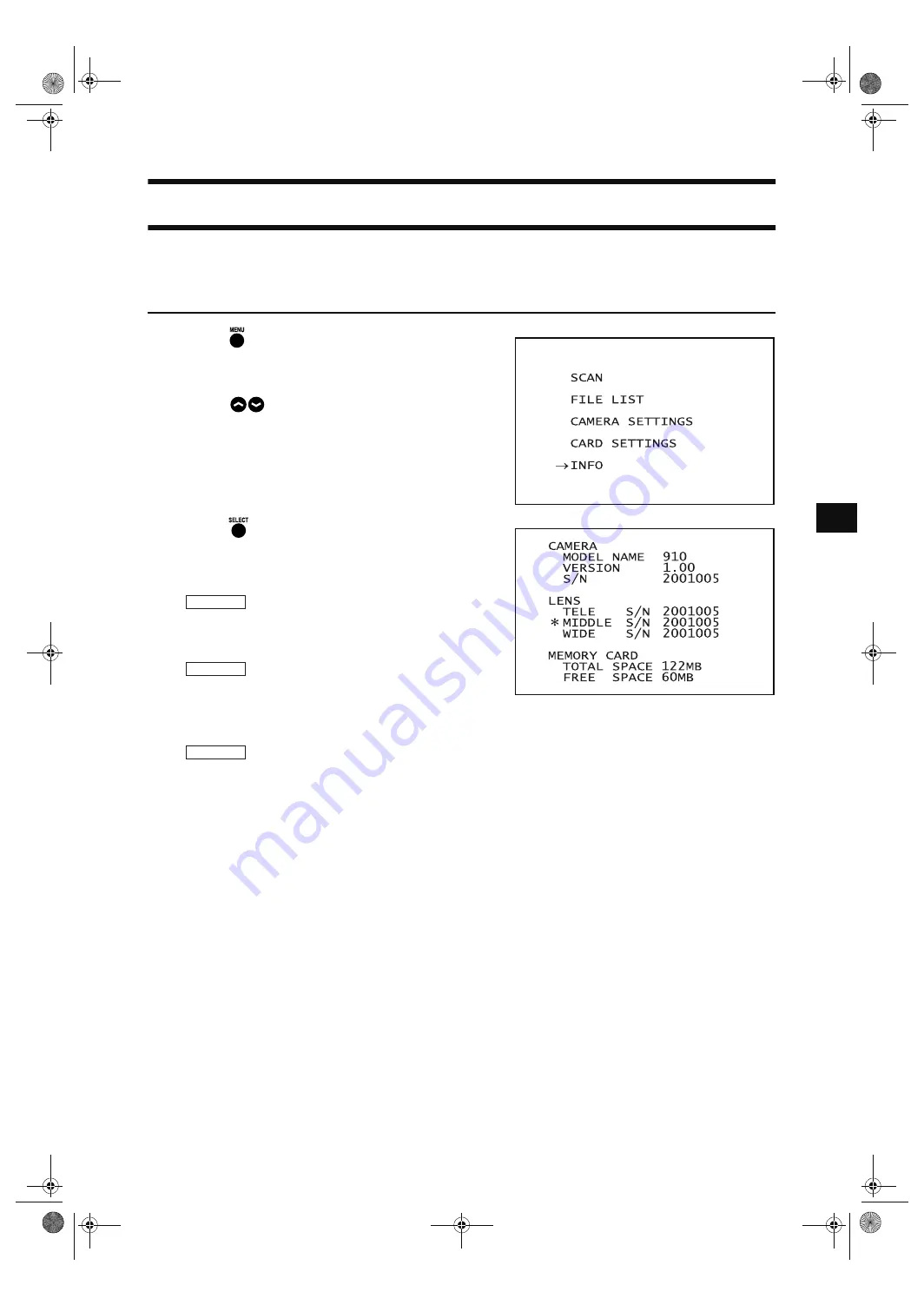
Displaying the Status Information

The model name, version, lens information, total capacity and unoccupied capacity of the memory card can be
displayed.

[Operating Procedure]

1

Press .

The MENU view will appear.

2

Press 

 to locate the arrow cursor to “IN-

FO”.

3

Press .

The status information will be displayed as shown be-
low.

MODEL NAME: 

Model name (VIVID 910)

VERSION:

 Version No.

S/N: 

Serial No.

TELE S/N:

 TELE lens’s serial No.

MIDDLE S/N:

 MIDDLE lens’s serial No.

WIDE S/N: 

WIDE lens’s serial No.

*:

 Indicates the currently installed lens.

TOTAL SPACE: 

Total capacity of memory card

FREE SPACE:

 Unoccupied capacity of memory card

CAMERA

LENS

PC CARD

Vivid910-hard-E.book  Page 51  Thursday, September 25, 2003  6:49 PM

Summary of Contents for Vivid 910

Page 1: ...I 910 Instruction Manual HARDWARE NOTE The VI 910 is model name for Europe and the VIVID 910 is model name for other countries Please note that the VIVID 910 model name is intended only for reference...

Page 2: ...manual are their trademarks or registered trademarks Contents and display examples given in this manual are subject to change The name MINOLTA or MINOLTA CO LTD and its associated logo used in this m...

Page 3: ...dirt or dust has entered through the vent holes Doing so may result in a fire For periodic inspection contact the nearest KONICA MINOLTA SENS ING authorized service facility When disconnecting the AC...

Page 4: ...mW 690nm CLASS 1 LASER PRODUCT CLASS 2 LASER PRODUCT Complied with IEC Publication 60825 1 1993 Amendment 2 2001 AVOID EXPOSURE Laser radiation is emitted from this aperture Complies with 21 CFR Chapt...

Page 5: ...uses and can radiate radio frequency energy and if not installed and used in accordance with the instruction manual may cause harmful interference to radio communications Operation of this equipment i...

Page 6: ...lacing Procedure 27 Scanning the Object 30 Displaying the Scan Results 32 High Quality Mode 33 Setting Focus Lock 35 Setting Manual Focus 36 Adjusting the Laser Power and CCD Gain Manually 37 Setting...

Page 7: ...5 Chapter 1 Before Using the Instrument Vivid910 hard E book Page 5 Thursday September 25 2003 6 49 PM...

Page 8: ...in Body Polygon Editing Tool White Balance Cap VI A10 AC Power Cord Lens 3 types with Lens Case Laser Barrier SCSI Cable VI A20 SCSI Conversion Connector V1 A21 Half pitch D sub 50 pin male plug 50 pi...

Page 9: ...NSING author ized service facility Memory Card Compact Flash Memory Card VI A31 PC Card Rotary Stage Set Adapter VI A32 Tripod Panhead Bench Top Frame Set Information about the recommended tripod panh...

Page 10: ...Compact Flash Memory Card VI A31 PC Card Adapter VI A32 White Balance Cap VI A10 AC Power Cord VIVID 910 Main Body Laser Barrier 3 types of lens with Lens Case Rotary Stage Set Bench Top Frame Set Pol...

Page 11: ...o not stare into this window Laser Emitting Window AC Power Connector Power Switch SCSI Port Viewfinder Operation Panel Memory Card Slot Handle The handle can be detached by re moving the four screws...

Page 12: ...to another displayed on the viewfinder 9 COLOR MONO key Switches the image on the viewfinder from color to monochrome or vice ver sa 0 FINE FAST key Switches scan mode from FINE to FAST or vice versa...

Page 13: ...11 Chapter 2 Preparation Vivid910 hard E book Page 11 Thursday September 25 2003 6 49 PM...

Page 14: ...power cord s plug always hold the plug and pull it to remove it Never pull the AC power cord itself as it may be damaged resulting in fire or electric shock Also do not insert or disconnect the AC po...

Page 15: ...be displayed on the viewfinder Note When turning power ON again after it has been turned OFF wait at least 5 seconds before doing so Failure to ob serve this may result in malfunction or breakdown of...

Page 16: ...e power switch to OFF Power will be turned OFF 2 Attach the laser barrier Note To ensure safety the laser barrier must be kept attached when the VIVID 910 is not in use POWER AC IN SCSI Vivid910 hard...

Page 17: ...case press any key and proceed to step 4 to set the date and time The backup battery for the date time data is charged while the power to the instrument is ON Setting Procedure 1 Press The MENU view...

Page 18: ...follows 8 Repeat steps 6 and 7 until all the desired date time items are set or changed Memo To cancel date time setting and restore the previous date time setting press 9 Press Setting is now complet...

Page 19: ...Set the power switch of both VIVID 910 and computer to OFF Note If the AC power cord is connected to an AC outlet with the power switch set to ON I damage to the VIVID 910 or computer may result Befor...

Page 20: ...omputer via the SCSI interface make sure that the SCSI ID No of the VIVID 910 differs from those set for the devices Setting Procedure 1 Press The MENU view will appear 2 Press to locate the arrow cur...

Page 21: ...s not the last device of those connected in series and ENABLE must be selected if it is not connected via the SCSI interface An error message will appear if DISABLE is selected even though the VIVID 9...

Page 22: ...20 Connecting the VIVID 910 to a Computer 7 Press Setting is now complete Vivid910 hard E book Page 20 Thursday September 25 2003 6 49 PM...

Page 23: ...scription of data file management saving loading selecting etc refer to pages 45 to 50 Inserting Ejecting the PC Card Adapter 1 When inserting the compact flash memory card into the PC card adapter ma...

Page 24: ...in accidents Mounting to the Tripod 1 Mounting the Tripod base plate to the Instrument Before mounting the instrument to the tripod mount the tripod base plate to the instrument as explained below Me...

Page 25: ...e instrument and secure them with two screws U3 8 sup plied with the accessory plate Attaching to the Panhead 1 Make sure that the tripod panhead is secured in place 2 Remove the rubber feet on the ba...

Page 26: ...24 Notes When Using the Instrument with Tripod Vivid910 hard E book Page 24 Thursday September 25 2003 6 49 PM...

Page 27: ...25 Chapter 3 Operation Vivid910 hard E book Page 25 Thursday September 25 2003 6 49 PM...

Page 28: ...to roughness on the surface of the object can be reduced if the object is positioned far from the VIVID 910 Select the most suitable lens by referring to the table given below WIDE Lens MIDDLE Lens T...

Page 29: ...operations e g saving data must be completed Do not touch the lens surface with fingers If dust or dirt has collected on the lens surface remove it using a camera air blower etc Dust or dirt on the l...

Page 30: ...wfind er as shown on the right Check the serial number of each lens displayed 4 Attach the desired lens Remove the lens cap Align the red mark on the lens with the one on the lens mount socket and ins...

Page 31: ...he hood Memo The hood must be turned until it contacts the bayonet mount socket 7 Press any key After approximately 10 seconds PLEASE OPEN LASER BARRIER AND PRESS ANY KEY will be displayed on the view...

Page 32: ...rocedure 1 Press The MENU view will appear 2 Press to locate the arrow cursor to SCAN 3 Press The color image currently captured by the VIVID 910 will appear on the viewfinder Memo Auto focus will be...

Page 33: ...ng just after the mode is switched from FINE to FAST or vice versa the motor will start rotation to set the laser beam first and then focus is performed For a description of displaying the scan result...

Page 34: ...aptured scan results range image data will be displayed on the viewfinder 1 Range image 2 Effective scan range back forth direction Displays the allowed scan range 3 Scan mode Displays the scan mode F...

Page 35: ...ty Mode when you read in memory card data that was scanned at a VIVID 910 the instrument will automatically eliminate all data values that are outside the measurement range This will be true even if H...

Page 36: ...quality mode is set to ON data outside the measurement range will be eliminated therefore it will not be displayed on the screen If the part that you want to input is displayed in yellow or does not...

Page 37: ...be auto focused For a description of manual focus refer to page 36 Operating Procedure The following procedure applies only if an error has occurred when a scan was performed as explained on page 30 1...

Page 38: ...rm manual focus For a description of focus lock refer to page 35 Operating Procedure 1 Measure the distance to the object with a mea suring tape Memo Although the front of the lens is the reference po...

Page 39: ...in must be adjusted manually Operating Procedure The following procedure must be carried out if images acquired when scan was performed as explained on page 30 are unsatisfactory 1 Press at the end of...

Page 40: ...ence dis tance refer to page 39 6 Press The monochrome image currently captured by the VIVID 910 will be focus locked and displayed in real time on the viewfinder Memo A color still image can also be...

Page 41: ...ly set laser power will turn to pink For a description of adjusting the laser power refer to page 37 2 Press The currently set CCD gain will turn to pink For a description of adjusting the CCD gain re...

Page 42: ...ith the newly set scan reference position Memo If the acquired image still lacks a front or back part of the object try the following If you are using the TELE or MIDDLE lens replace it with the WIDE...

Page 43: ...he MENU view will appear 2 Press to locate the arrow cursor to CAMERA SETTINGS 3 Press The CAMERA SETTINGS view will appear 4 Press to locate the arrow cursor to AU TO READ 5 Press The currently set a...

Page 44: ...arrow cursor to COLOR 5 Press The currently set color level will turn to pink 6 Press to set the desired laser power Settings AUTO Scans a color image with the same exposure level as the one for monoc...

Page 45: ...uency fluo rescent lamp Memo The white balance has been adjusted under fluorescent light before shipment Operating Procedure 1 Set the light source so that the lighting condition is the same as that u...

Page 46: ...s CALIBRATING will be displayed and white balance will be adjusted Memo If DEFAULT is selected and is pressed at step 6 the default white balance i e calibrated under fluorescent light will be restore...

Page 47: ...d Two methods are available for assigning a file name to image data when saving it AUTO to assign file names automatically and INTERACTIVE to assign them interactively Operating Procedure 1 Press The...

Page 48: ...acter to be changed from the prefix file name dis played in by pressing Memo Moving through the prefix file name from one character to another by pressing the character located right on will be cleare...

Page 49: ...od has been selected RECORDING will be displayed and the data will be saved If INTERACTIVE file name input method has been selected proceed to step 3 3 If INTERACTIVE file name input method has been s...

Page 50: ...to load 5 Press to check the information regarding the selected file LOADING will be displayed and the following views will appear Memo Each time is pressed the view will switch as follows Even if a...

Page 51: ...urn to pink 5 Press to select the character to be changed Memo Moving through the prefix file name from one character to another by pressing the character located right on will be cleared 6 Press to s...

Page 52: ...ppear 3 Press to locate the arrow cursor to DE LETE FILE 4 Press The selected file name will turn to pink and CON FIRM TO DELETE will be displayed Note Once a file is deleted it cannot be restored any...

Page 53: ...IN FO 3 Press The status information will be displayed as shown be low MODEL NAME Model name VIVID 910 VERSION Version No S N Serial No TELE S N TELE lens s serial No MIDDLE S N MIDDLE lens s serial N...

Page 54: ...52 Displaying the Status Information Vivid910 hard E book Page 52 Thursday September 25 2003 6 49 PM...

Page 55: ...53 Chapter 4 Appendix Vivid910 hard E book Page 53 Thursday September 25 2003 6 49 PM...

Page 56: ...the serial No of the lens and replace the lens properly CLOCK ERROR PRESS ANY KEY The clock is abnormal Press any key The date time data will be initialized so set it again DIRECTORY FULL PLEASE INSE...

Page 57: ...till does not disap pear contact a KONICA MINOLTA SENSING authorized service facility TERMINATE ERROR PRESS ANY KEY SET TERMINATE ENABLE SCSI terminator error has occurred Press any key and set the te...

Page 58: ...cess is repeated by scanning the stripe light vertically on the object surface using a Galvano mirror to obtain a 3D image data of the object In addition a color image of the object is also obtained b...

Page 59: ...ally saved in the frame memory Time center of gravity and Space center of gravity Time center of gravity is the center of gravity of the variation in the LD light passing CCD s one picture ele ment ov...

Page 60: ...58 Dimension Diagram 271 286 7 223 462 1 412 6 Unit mm Vivid910 hard E book Page 58 Thursday September 25 2003 6 49 PM...

Page 61: ...X 1 40 mm Y 1 04 mm Z 0 40 mm to the Z reference plane Conditions FINE mode distance 0 6 m KONICA MINOLTA SENSING s standard 3D chart KONICA MINOLTA SENSING s processing software temperature 20 C rela...

Page 62: ...ge temperature range of 10 to 40 C 50 F to 104 F at relative humidity 65 or less with no condensation For North America temperature range of 10 to 40 C and relative humidity 50 or less at 40 C with no...

Page 63: ...Vivid910 hard E hyou fm Page 3 Thursday September 25 2003 6 52 PM...

Page 64: ...2001 2006 KONICA MINOLTA SENSING INC AGKCKK 7 Printed in Japan 9222 1888 40 8KXKF JCTF J QW HO...

Reviews: