background image

451106/B

189

External synchronisation

The Processing Unit (PU) is equipped with a connection for interface to an external
synchronisation system.

This connection is used for interface to an external synchronisation system (for example
K-Sync) used when multiple echo sounders are employed on the same vessel. The
external synchronisation connector is located on the CBMF board of the processing
unit. The connector is RJ45 type.

A

Local connection The connector is RJ45 type.

Note

Pin 3 and 6 is used by Kongsberg Maritime only.

B

Connection on remote device

Unless otherwise specified, this cable must be provided by the installation shipyard.

Minimum cable requirements

Conductors

: 2 x 3 x 0.2 mm²

Screen

: Overall braided

Voltage

: 30 V

Maximum outer diameter

: Defined by the plugs and/or the cable gland

We recommend using a shielded CAT-6A quality or better cable.

Cable layout and interconnections

Summary of Contents for EM 712

Page 1: ...451106 B November 2019 Kongsberg Maritime AS Kongsberg EM 712 Multibeam echo sounder Maintenance Manual ...

Page 2: ...signed Improper use or maintenance may cause damage to the equipment and or injury to personnel You must be familiar with the contents of the appropriate manuals before attempting to operate or work on the equipment Kongsberg Maritime disclaims any responsibility for damage or injury caused by improper installation use or maintenance of the equipment Disclaimer Kongsberg Maritime AS endeavours to ...

Page 3: ...box 19 BIST Built In Self Test theory 22 BIST Introduction 23 CPU Test 24 CBMF test 25 RX unit test 26 TX unit test 27 CBMF CPU link 28 RX CBMF link 29 RX channels 30 TX channels 31 RX noise level 32 RX noise spectrum 33 Software date and versions 34 System information 34 PREVENTIVE MAINTENANCE 35 Inspecting and cleaning the transducer face 36 Painting the transducer face 38 Inspecting and replaci...

Page 4: ... List of spare parts Processing Unit 66 Processing Unit spare part 401290 66 CBMF board spare part 404291 66 CPU board spare part 456983 67 Power supply spare part 373897 67 Fan unit spare part 385387 68 List of spare parts Transmitter Unit 69 LPTX36 Transmitter board spare part 390018 69 TX RIO board spare part 399431 69 RIO P board spare part 322623 70 Ethernet switch spare part 338124 70 TXU Fa...

Page 5: ...mitter Unit top panel description 91 RIO P board dip switch setting 92 RECEIVER UNIT 93 Receiver Unit description 94 Receiver Unit front panel description 95 Receiver Unit dip switch setting 96 HYDROGRAPHIC WORK STATION 98 Hydrographic Work Station description 99 Hydrographic Work Station front panel description 99 Hydrographic Work Station rear panel description 100 DRAWING FILE 101 216148 Transd...

Page 6: ...requirements 140 Interface specifications Hydrographic Work Station all format 141 Interface specifications Hydrographic Work Station KMall format 141 Weight and outline dimensions 142 Power requirements 145 Environmental requirements 146 Alignment specifications 149 CABLE LAYOUT AND INTERCONNECTIONS 151 Read this first 152 Cable plans 153 Cable plan Processing Unit 154 Cable plan Transmitter Unit...

Page 7: ...nsducer array flatness 203 Checking the transducer array flatness and correcting deviations 204 Calibration 205 Vessel coordinate system 206 EQUIPMENT HANDLING 208 Transporting Kongsberg Maritime equipment 209 Lifting units and transportation boxes 210 Inspection of units and transportation boxes after arrival 212 Specifications for storage prior to installation or use 213 Unpacking instructions 2...

Page 8: ...8 451106 B Kongsberg EM 712 ...

Page 9: ...tional troubleshooting on electronic and mechanical products We assume that you are familiar with the basic acoustic principles of sound in water We also expect that you have some experience with multibeam split beam and or single beam echo sounders in scientific applications Online information All relevant end user documentation provided for your EM 712 can be downloaded from our website https ww...

Page 10: ...10 451106 B Kongsberg EM 712 Topics System description page 11 EM 712B upgrade from EM 710 page 11 System diagram 0 25 x 0 5 system page 12 System units page 14 Kongsberg EM 712 Maintenance Manual ...

Page 11: ... be configured for 0 5 using two receiver modules For upgrade from EM 710 to EM 712 the TX and RX frames plus the transmit array s can be reused Acrosstrack coverage swath width is up to 5 5 times water depth and the maximum achievable depth is 3600 m The sounding density is very high allowing even the very demanding LINZ special order survey specification for object detection to be met in full Th...

Page 12: ...system diagram identifies the main components of a basic EM 712 system Only the main connections between the units are shown Detailed interface capabilities and power cables are not shown A Hydrographic Work Station Kongsberg EM 712 Maintenance Manual ...

Page 13: ... D Interfaces Positioning systems Attitude roll pitch and heave Sound speed sensor With K Controller upgrade Velocity Heading Clock Trigger input output Clock synchronisation 1PPS E Transmitter Unit F Receiver Unit G Transmit transducer module H Receive transducer module Kongsberg EM 712 ...

Page 14: ... the vessel s hull Mills Cross configuration The transmit transducer array should be aligned parallel to the vessel s keel The receiver transducer array should be aligned 90 on the keel Both transducer arrays should be horizontal on a plane on the keel Processing Unit description The EM 712 Processing Unit is provided to process the signals to and from the Transmitter and Receiver Units The EM 712...

Page 15: ... EM 712 Transmitter Unit has all transmit electronics like control processors power amplifiers power supply capacitor battery and Ethernet interface The Transmitter Unit is a wall mounted steel cabinet with integrated shock and vibration absorbers designed for bulkhead mounting One 19 inch sub rack is contained in the cabinet The number of circuit boards in the sub rack will depend on the chosen t...

Page 16: ... 0 5 transducer array two Receiver Units are used With EM 712B it is possible to upgrade EM 710 to EM 712 without replacing the transducer modules To achieve this we have made a separate Receiver Unit scientifically tailored for use with the EM 710 receive transducers The EM 712B Receiver Unit has the same measurements and weight as the regular Receiver Unit Hydrographic Work Station description T...

Page 17: ...451106 B 17 Troubleshooting Topics Tools for troubleshooting page 18 BIST Built In Self Test dialog box page 19 BIST Built In Self Test theory page 22 Troubleshooting ...

Page 18: ...ctronic and electromechanical tasks This includes different screwdriver types pliers spanners a cable stripper a soldering iron etc Each tool must be provided in various sizes We recommend that all tools are demagnetized to protect your equipment Note If one or more special tools are required for a task these are specified in the relevant procedure It is impossible to create a detailed list of all...

Page 19: ...n Parameters on the View menu Select the Installation Parameters icon and select BIST K Controller Select the Installation Parameters icon and select BIST Description The BIST Built In Self Test options provide a number of automatic tests that may be started to check the operation of the echo sounder system Various test are available depending on what system you have Troubleshooting ...

Page 20: ...allel bus interface between the CBMF board s and the CPU circuit board A large set of known data is transferred from the CPU unit on Ethernet via CBMF back to the CPU board The data received is checked by the CPU board RX CBMF link This test checks the GBit interface between the RX unit and the CBMF boards A large set of known data is transferred from RX unit via CBMF to the CPU board on parallel ...

Page 21: ...nels In addition the average level for all channels are displayed This spectrum test can be used to search for external noise sources Software date and versions This test presents the software date and versions for the system components System information This test acquires information needed serial numbers software versions BIST results etc for a status report Save tests and open folder Select Sa...

Page 22: ...24 CBMF test page 25 RX unit test page 26 TX unit test page 27 CBMF CPU link page 28 RX CBMF link page 29 RX channels page 30 TX channels page 31 RX noise level page 32 RX noise spectrum page 33 Software date and versions page 34 System information page 34 Kongsberg EM 712 Maintenance Manual ...

Page 23: ...nized in a sequence and tests module by module The CPU executes the BISTs and sends the BIST reply to the operator station Temperature voltage communication and firmware versions of each board and module are tested A Processing Unit B Transmitter Unit TXU C Receiver Unit D Transmit transducer array E Receive transducer array Troubleshooting ...

Page 24: ... for the CPU die and for the CPU board Checks all beamformer and signal processing boards CBMF in the EM 712 Processing Unit In addition some key voltages are reported and finally the network addresses for the board s interfaces Dark green modules are to be tested Light green modules have to function to be able to perform current test Kongsberg EM 712 Maintenance Manual ...

Page 25: ... EM 712 Processing Unit This test presents the CBMF board temperature the internal power supply voltages In addition software and firmware versions are displayed Dark green modules are to be tested Light green modules have to function to be able to perform current test Troubleshooting ...

Page 26: ...This test presents the internal temperatures and voltages in the receiver electronics In addition software and firmware versions are displayed Dark green modules are to be tested Light green modules have to function to be able to perform current test Kongsberg EM 712 Maintenance Manual ...

Page 27: ...mitter Unit This test presents the internal temperatures and voltages in the transmitter electronics In addition software and firmware versions are displayed Dark green modules are to be tested Light green modules have to function to be able to perform current test Troubleshooting ...

Page 28: ...rallel bus interface between the CBMF board s and the CPU circuit board A large set of known data is transferred from the CPU unit on Ethernet via CBMF back to the CPU board The data received is checked by the CPU board Dark green modules are to be tested Light green modules have to function to be able to perform current test Kongsberg EM 712 Maintenance Manual ...

Page 29: ...nd the CBMF boards A large set of known data is transferred from RX unit via CBMF to the CPU board on parallel bus The data received is checked by the CPU board Dark green modules are to be tested Light green modules have to function to be able to perform current test Troubleshooting ...

Page 30: ...s The BIST report displays the measured RX transducer impedance for all RX channels EM 712B The Receiver Unit has a programmable signal generator board that is used to inject a test signal at the preamplifier inputs in the Receiver Unit The BIST report displays the measured RX transducer impedance for all RX channels Dark green modules are to be tested Light green modules have to function to be ab...

Page 31: ...sducers This test checks the impedance of all TX elements This is done by measuring the voltage and current used by all individual transmitters Dark green modules are to be tested Light green modules have to function to be able to perform current test Troubleshooting ...

Page 32: ...ceiver channel in dB rel 1 μPa Hz for different frequency bands The receiver directivity index the transducer sensitivity and the filter bandwidth is used to convert to isotropic spectral noise level Dark green modules are to be tested Light green modules have to function to be able to perform current test Kongsberg EM 712 Maintenance Manual ...

Page 33: ...he RX noise level test The noise spectrum level is displayed for small frequency bands for groups of 32 channels In addition the average level for all channels are displayed This spectrum test can be used to search for external noise sources Dark green modules are to be tested Light green modules have to function to be able to perform current test Troubleshooting ...

Page 34: ...re to be tested Light green modules have to function to be able to perform current test System information Generates a status report for the EM 712 system This test acquires information needed serial numbers software versions BIST results etc for a status report This report can be sent to the factory to update the EM 712 product database Kongsberg EM 712 Maintenance Manual ...

Page 35: ...ve maintenance Topics Inspecting and cleaning the transducer face page 36 Painting the transducer face page 38 Inspecting and replacing sacrificial anodes page 40 Approved anti fouling paints page 41 Preventive maintenance ...

Page 36: ...ant to check the transducer for physical damage Any cracks fractures or holes in the red protective coating may result in a water leak and a leak may cause irreparable damage to the transducer A transducer must always be handled as a delicate instrument Incorrect actions may damage the transducer beyond repair Observe these transducer handling rules Do not activate the transducer when it is out of...

Page 37: ... skin of the transducer face 3 Allow the transducer surface to dry 4 Do a thorough visual inspection of the transducer Check for dents scratches holes or other damage to the surface If you suspect damage take a high resolution photo Contact your dealer or the Kongsberg support organization for advice 5 Apply anti fouling paint as described in the dedicated procedure Note Because some paint types m...

Page 38: ...er has not been designed with any protection against biological fouling Anti fouling paint may therefore be applied to the transducer face To minimize the negative acoustical effects the layer of anti fouling paint must be as thin as possible Note The anti fouling paint will reduce the acoustical performance of the transducer The surface roughness of the transducer substrate and the thickness of t...

Page 39: ...y the minimum specified film thickness per coat and for the complete layer It is not possible to measure dry film thickness on transducer surface You must therefore use a wet film gauge to frequently measure the paint thickness Note We strongly recommend that you do not use a paintbrush and or a roller 7 Allow the paint to dry Further requirements The contractor or shipyard must keep a daily paint...

Page 40: ...and zinc The sacrificial anodes must be inspected every time the vessel is in dry dock Replace the anodes if they are damaged or severely corroded Procedure 1 Inspect all anodes for damage and corrosion 2 Loosen the mounting screws and remove the anode 3 Clean the new anode and mounting surface using Isopropyl alcohol on a soft cloth or paper wipe 4 Grease the mounting screws and threads with Aqua...

Page 41: ...rer s website http www jotun com Products SeaQuantum Ultra S Primer Safeguard Universal ES Apply 80 µm wet film thickness 50 µm dry film thickness Paint SeaQuantum Ultra S Apply 250 µm wet film thickness 125 µm dry film thickness Seaforce 200 AV Primer Safeguard Universal ES AV Apply 70 µm wet film thickness 50 µm dry film thickness Paint Seaforce 200 AV Apply 140 µm wet film thickness 90 µm dry f...

Page 42: ...tersleek 1100SR Apply 150 µm dry film thickness Intersmooth 7465Si SPC Primer Intergard 269 Apply 40 µm dry film thickness Paint Intersmooth 7465Si SPC Apply 100 µm dry film thickness The list can also be found on Kongsberg Maritime https www kongsberg com mar itime Kongsberg EM 712 Maintenance Manual ...

Page 43: ... for parts replacement page 44 Processing Unit replacement page 46 CPU board replacement page 49 VadaTech CP219 Ethernet switch replacement page 52 CBMF board replacement page 55 Fan unit replacement page 58 Processing Unit fuse replacement page 61 Parts replacement ...

Page 44: ... electronic modules are delicate items They may work year after year in an advanced product but then fail due to a small spark of static electricity For this reason it is very important that they are properly handled and protected during handling You must be familiar with the applicable handling precautions Take all necessary steps to avoid Electrostatic Discharge ESD As a minimum the following pr...

Page 45: ... antistatic transportation container for example a static shielding bag before transportation 5 During installation and servicing all electrical equipment for example soldering irons and test equipment must be earthed WARNING Personell must check that all the equipment is earthed before power is connected or switched on Parts replacement ...

Page 46: ...ing device in the EM multibeam system It is provided to process the signals to and from the transducer s Note These procedures will instruct you to handle electronic circuit boards and or modules Before doing so make sure that you are familiar with the applicable handling precautions Follow the relevant handling procedures for circuit boards and electronic modules Topics Removing the Processing Un...

Page 47: ...protect your equipment Context Refer to the detailed information in the Cable layout and interconnections chapter Procedure 1 Locate the unit you wish to remove The Processing Unit is normally mounted in a cabinet in a rack or placed on a table 2 Turn off the EM 712 3 Disconnect the power cable on the rear side of the unit 4 Disconnect the cables 5 Loosen the unit by removing the mounting bolts on...

Page 48: ...ls are demagnetized to protect your equipment Context Refer to the detailed information in the Cable layout and interconnections chapter Procedure 1 Grab a firm hold of the unit and push it straight in 2 Fasten the unit by securing the mounting bolts on both sides 3 Connect the power cable on the rear side of the unit 4 Connect the cables Note When you connect the cables make sure that they are al...

Page 49: ...ay look slightly different due to minor design changes on the protective lid and or the front panel There is one CPU board in the Processing Unit Note These procedures will instruct you to handle electronic circuit boards and or modules Before doing so make sure that you are familiar with the applicable handling precautions Follow the relevant handling procedures for circuit boards and electronic ...

Page 50: ...rs etc Each tool must be provided in various sizes We recommend that all tools are demagnetized to protect your equipment Context Removal is done by pulling the board straight out of the Processing Unit Procedure 1 Turn off the Processing Unit 2 Disconnect the power cable on the rear side of the unit 3 Identify the circuit board you wish to remove 4 Disconnect all relevant cables 5 Loosen the scre...

Page 51: ...ools This tool set must comprise the normal tools for electromechanical tasks This includes different screwdriver types pliers adjustable spanners etc Each tool must be provided in various sizes We recommend that all tools are demagnetized to protect your equipment Depending on the chosen installation method additional tools may be required Procedure 1 Make sure that all AC mains power has been di...

Page 52: ...h CP219 board is used as an Ethernet switch in the EM 712 Processing Unit Note These procedures will instruct you to handle electronic circuit boards and or modules Before doing so make sure that you are familiar with the applicable handling precautions Follow the relevant handling procedures for circuit boards and electronic modules Topics Removing the VadaTech CP219 Ethernet switch page 53 Insta...

Page 53: ...We recommend that all tools are demagnetized to protect your equipment Context Removal is done by pulling the board straight out of the Processing Unit Procedure 1 Turn off the Processing Unit 2 Disconnect the power cable on the rear side of the unit 3 Identify the circuit board you wish to remove 4 Disconnect all relevant cables 5 Loosen the screws A 6 Loosen the circuit board by pushing the red ...

Page 54: ...the normal tools for electromechanical tasks This includes different screwdriver types pliers adjustable spanners etc Each tool must be provided in various sizes We recommend that all tools are demagnetized to protect your equipment Procedure 1 Make sure that all AC mains power has been disconnected 2 Grab the handle and push the circuit board straight in 3 Push the handle to the left C 4 Tighten ...

Page 55: ...Beamformer CBMF board is used by the Processing Unit for beamforming and signal processing purposes Note These procedures will instruct you to handle electronic circuit boards and or modules Before doing so make sure that you are familiar with the applicable handling precautions Follow the relevant handling procedures for circuit boards and electronic modules Topics Removing the CBMF board page 56...

Page 56: ...tools are demagnetized to protect your equipment Context There are one or two Compact Beamformer CBMF boards in the Processing Unit The number of CBMF boards depend upon the configuration of the EM 712 system Removal is done by pulling the board straight out of the Processing Unit Procedure 1 Turn off the Processing Unit 2 Disconnect the power cable on the rear side of the unit 3 Identify the circ...

Page 57: ...omechanical tasks This includes different screwdriver types pliers adjustable spanners etc Each tool must be provided in various sizes We recommend that all tools are demagnetized to protect your equipment Context There are one or two Compact Beamformer CBMF boards in the Processing Unit The number of CBMF boards depend upon the configuration of the EM 712 system Procedure 1 Make sure that all AC ...

Page 58: ...s The Processing Unit has two fan units for cooling purposes Note These procedures will instruct you to handle electronic circuit boards and or modules Before doing so make sure that you are familiar with the applicable handling precautions Follow the relevant handling procedures for circuit boards and electronic modules Topics Removing the fan unit page 59 Installing the fan unit page 60 Kongsber...

Page 59: ...pliers adjustable spanners etc Each tool must be provided in various sizes We recommend that all tools are demagnetized to protect your equipment Context The Processing Unit has two fan units for cooling purposes Procedure 1 Turn off the Processing Unit 2 Disconnect the power cable on the rear side of the unit 3 Locate the unit you wish to remove 4 Loosen the screw A 5 Grab the handle and pull the...

Page 60: ...asks This includes different screwdriver types pliers adjustable spanners etc Each tool must be provided in various sizes We recommend that all tools are demagnetized to protect your equipment Context The Processing Unit has two fan units for cooling purposes Procedure 1 Make sure that all AC mains power has been disconnected 2 Grab the handle and push the unit straight in B 3 Tighten the screw A ...

Page 61: ...e procedures will instruct you to handle electronic circuit boards and or modules Before doing so make sure that you are familiar with the applicable handling precautions Follow the relevant handling procedures for circuit boards and electronic modules Topics Removing the fuse in the Processing Unit page 62 Installing the fuse in the Processing Unit page 63 Parts replacement ...

Page 62: ...omechanical tasks This includes different screwdriver types pliers adjustable spanners etc Each tool must be provided in various sizes We recommend that all tools are demagnetized to protect your equipment Procedure 1 Turn off the Processing Unit 2 Disconnect the power cable on the rear side of the unit 3 Locate the fuse holder 4 Insert a small blade screwdriver into the side of the fuse holder to...

Page 63: ...s for electromechanical tasks This includes different screwdriver types pliers adjustable spanners etc Each tool must be provided in various sizes We recommend that all tools are demagnetized to protect your equipment Procedure 1 Make sure that all AC mains power has been disconnected 2 Insert a new fuse into the fuse holder 3 Push the fuse holder in 4 Connect the power cable on the rear side of t...

Page 64: ...rts and consumables Topics Ordering spare parts page 65 List of spare parts Processing Unit page 66 List of spare parts Transmitter Unit page 69 List of spare parts Receiver Unit page 71 Kongsberg EM 712 Maintenance Manual ...

Page 65: ...ing information must be provided with your order Part name and or description Our part number Number of items required Your shipment address Preferred shipment method Required date of delivery from us For certain spare parts typically complete units printed circuit boards and software the vessel name is also useful as this allows us to update our vessel database Spare parts and consumables ...

Page 66: ...ended number in spare 1 True manufacturer Kongsberg Maritime https www kongsberg com maritime Related topics Processing Unit replacement page 46 CBMF board spare part 404291 There are two Compact Beamformer CBMF boards in the Processing Unit This is a generic photo The CBMF board used by the EM 712 may look slightly different due to minor design changes on the protective lid and or the front panel...

Page 67: ...rer Concurrent Technologies Plc Concurrent Technologies http www gocct com Related topics CPU board replacement page 49 Power supply spare part 373897 One power supply unit is used in the EM 712 Processing Unit for supply of 5 24 and 48 VDC Part name Power supply Excesys XLB Part number 373897 Number in use 1 Recommended number in spare 1 True manufacturer Excelsys Excelsys Technologies http www e...

Page 68: ...e used in the EM 712 Processing Unit for side to side cooling Part name Fan unit Part number 385387 Number in use 2 Recommended number in spare 1 True manufacturer Recab Schroff Related topics Fan unit replacement page 58 Kongsberg EM 712 Maintenance Manual ...

Page 69: ...spare part 390018 There are up to 20 LPTX36 Transmitter boards in each Transmitter Unit Part name LPTX36 Transmitter board Part number 390018 Number in use 20 Recommended number in spare 1 True manufacturer Kongsberg Maritime https www kongsberg com maritime TX RIO board spare part 399431 There are up to 10 TX RIO boards in each Transmitter Unit Part name TX RIO board Part number 399431 Number in ...

Page 70: ...24 Number in use 1 Recommended number in spare 1 True manufacturer VadaTech Incorporated VadaTech http www vadatech com TXU Fan unit spare part 397740 There is one fan unit in each Transmitter Unit Part name TXU Fan unit Part number 397740 Number in use 1 Recommended number in spare 1 True manufacturer Elma https www elma com TXU Power supply spare part 422238 There is one power supply unit in eac...

Page 71: ...824 page 74 Receiver Unit 1 spare part 403302 The complete receiver Unit can be supplied as a spare part The number of Receiver Units used will depend on the system configuration The number of circuit boards in the Receiver Unit will depend on the chosen transducer configuration Part name Receiver Unit 1 Part number 403302 Number in use 1 Recommended number in spare 1 True manufacturer Kongsberg M...

Page 72: ... will depend on the system configuration The number of circuit boards in the Receiver Unit will depend on the chosen transducer configuration Part name Receiver Unit 2 Part number 403303 Number in use 1 Recommended number in spare 1 True manufacturer Kongsberg Mar itime https www kongsberg com maritime Kongsberg EM 712 Maintenance Manual ...

Page 73: ...ded number in spare 1 True manufacturer Kongsberg Mar itime https www kongsberg com maritime EM 712B Receiver Unit 2 spare part 448220 The complete receiver Unit can be supplied as a spare part The number of Receiver Units used will depend on the system configuration The number of circuit boards in the Receiver Unit will depend on the chosen transducer configuration EM 712B is an upgrade kit for E...

Page 74: ...24 There is one power supply unit in each Receiver Unit Part name Power supply Roal RCB600 AB00 Part number 399824 Number in use 1 Recommended number in spare 1 True manufacturer Roal Efore https www efore com Kongsberg EM 712 Maintenance Manual ...

Page 75: ...6 Processing Unit familiarization page 76 Processing Unit front panel description page 77 Processing Unit rear panel description page 78 Processing Unit circuit boards and modules page 79 CPU board page 80 CP219 Ethernet switch page 83 CBMF board page 85 Processing Unit ...

Page 76: ...or station via Ethernet The 48 V output from the Processing Unit can be used for remote on off control of the Transmitter and Receiver Units The Processing Unit is normally located in a sonar room close to the transducer arrays The unit can also be placed in the survey room or on the bridge Processing Unit familiarization The Processing Unit consists of an instrument case with integrated rack moun...

Page 77: ...451106 B 77 Processing Unit front panel description The front panel of the Processing Unit holds a mains power switch and an information display A Information display B Power On Off Processing Unit ...

Page 78: ...e Processing Unit has two fan units for cooling purposes B Remote Control connector C 48 Vdc output connector D Ground connector E AC mains power socket F Fuse for the AC mains supply G CPU board H CBMF board There are one or two Compact Beamformer CBMF boards in the Processing Unit The number of CBMF boards depend upon the configuration of the EM 712 system I CP219 Ethernet switch J Air filter un...

Page 79: ...amformer CBMF board is used by the Processing Unit for beamforming and signal processing purposes There are one or two Compact Beamformer CBMF boards in the Processing Unit The number of CBMF boards depend upon the configuration of the EM 712 system C VadaTech CP219 board The VadaTech CP219 board is used as an Ethernet switch in the EM 712 Processing Unit D Fan unit The Processing Unit has two fan...

Page 80: ...verview Concurrent PP B12 is one version of CPU board used in the EM 712 Processing Unit The Concurrent PP B12 is a PC compatible high functionality Compact PCI cPCI board used by the EM 712 Processing Unit as the Central Processing Unit CPU The circuit board is manufactured by Concurrent Technologies and configured by Kongsberg Maritime AS Different CPU boards can be used in the EM 712 Processing...

Page 81: ...rnet 1 used for communication to the Operator Station Hydrographic Work Station Concurrent PP833 CPU board overview Concurrent PP833 is one version of CPU board used in the EM 712 Processing Unit The Concurrent PP833 is a PC compatible high functionality Compact PCI cPCI board used by the EM 712 Processing Unit as the Central Processing Unit CPU The circuit board is manufactured by Concurrent Tech...

Page 82: ...e connectors are used in the EM 712 A PMC XMC1 Console for Kongsberg Maritime use only B COM1 to COM4 Four serial ports with RJ45 connectors The ports can be configured to be RS 232 or RS 422 C USB 2 not used D USB 1 not used E Ethernet 1 used for communication to the Operator Station Hydrographic Work Station F Ethernet 2 not used G USB 0 not used Kongsberg EM 712 Maintenance Manual ...

Page 83: ... board is used as an Ethernet switch in the EM 712 Processing Unit This is a generic photo The Vadatech CP219 board used by the EM 712 may look slightly different due to minor design changes on the protective lid and or the front panel The VadaTech CP219 is a compact PCI module that provides 10 Gigabit Ethernet ports on the front panel Processing Unit ...

Page 84: ...rd is fitted with the following connectors A Port 1 GbE0 Regular Gigabit Ethernet port B Port 2 GbE1 Regular Gigabit Ethernet port C Port 3 GbE2 Regular Gigabit Ethernet port D Port 4 GbE3 Regular Gigabit Ethernet port E Port 5 GbE4 Regular Gigabit Ethernet port F Port 6 GbE5 Regular Gigabit Ethernet port G Port 7 GbE6 Regular Gigabit Ethernet port H Port 8 GbE7 Regular Gigabit Ethernet port I Por...

Page 85: ...page 87 CBMF board overview The Compact Beamformer CBMF board is used by the Processing Unit for beamforming and signal processing purposes This is a generic photo The CBMF board used by the EM 712 may look slightly different due to minor design changes on the protective lid and or the front panel Processing Unit ...

Page 86: ... of the on board software the links and the switches it can be configured for specific use When a board is provided as a spare part it is readily configured This is a generic photo The CBMF board used by the EM 712 may look slightly different due to minor design changes on the protective lid and or the front panel Kongsberg EM 712 Maintenance Manual ...

Page 87: ... a spare CBMF board this is also set up correctly before it is shipped CBMF board connectors The CBMF board holds a large connector for the backplane as well as several front mounted connectors This is a generic photo The CBMF board used by the EM 712 may look slightly different due to minor design changes on the protective lid and or the front panel The CBMF board is fitted with the following con...

Page 88: ...er Unit Topics Transmitter Unit description page 89 Transmitter Unit bottom panel description page 89 Transmitter Unit top panel description page 91 RIO P board dip switch setting page 92 Kongsberg EM 712 Maintenance Manual ...

Page 89: ...tained in the cabinet The number of circuit boards in the sub rack will depend on the chosen transducer configuration Twisted pair Ethernet is used for data communication with the Processing Unit The Transmitter Unit is normally located in a sonar room close to the transducer arrays For a 0 25 transducer array two Transmitter Units are used Transmitter Unit bottom panel description The Transmitter...

Page 90: ...ation of the EM 712 system 0 25 TX array 20 2x10 0 5 TX array 10 1 TX array 5 2 TX array 3 RIO P board There is one RIO P board in each Transmitter Unit The signals for remote on off control and synchronization is connected to the RIO P board In addition there are two Ethernet connectors and connection for power at the bottom of the Transmitter Unit Kongsberg EM 712 Maintenance Manual ...

Page 91: ...ansmitter boards in each Transmitter Unit Each LPTX36 board is connected to the Ethernet switch in the Transmitter Unit The number of LPTX36 boards depends on the configuration of the EM 712 system 0 25 TX array 40 2x20 0 5 TX array 20 1 TX array 10 2 TX array 5 VadaTech CP218 Ethernet switch There is one VadaTech CP218 Ethernet switch in each Transmitter Unit Each LPTX36 board is connected to the...

Page 92: ...with the LED lights on the front of the RIO P board when the board is installed and the Transmitter Unit is powered up MASTER should be lit ID5 ID6 and ID7 should not be lit B Transmitter Unit 2 SLAVE Switch 1 and 4 must be set to OFF switch 2 and 3 must be set to ON Note If there is only one Transmitter Unit in the system it has to be set to Transmitter Unit 1 MASTER Kongsberg EM 712 Maintenance ...

Page 93: ...451106 B 93 Receiver Unit Topics Receiver Unit description page 94 Receiver Unit front panel description page 95 Receiver Unit dip switch setting page 96 Receiver Unit ...

Page 94: ...hosen transducer configuration Twisted pair Ethernet is used for data communication with the Processing Unit The Receiver Unit is normally located in a sonar room close to the transducer arrays For a 0 5 transducer array two Receiver Units are used With EM 712B it is possible to upgrade EM 710 to EM 712 without replacing the transducer modules To achieve this we have made a separate Receiver Unit ...

Page 95: ...nel description The connectors and circuit boards of the Receiver Unit are accessed from the front The transducer cables connect to the receiver Unit The number of cables will depend on the chosen transducer configuration Receiver Unit ...

Page 96: ...iver Unit has to be correct For a 0 5 transducer array two Receiver Units are used The software in the Processing Unit must know the identification of the Receiver Units A switch on the processing board inside the Receiver Unit is used for this Kongsberg EM 712 Maintenance Manual ...

Page 97: ...p Two Receiver Units A Receiver Unit 1 all switches must be set to OFF OFF is when they are pushed up Receiver Unit 1 is connected to RX transducer 1 B Receiver Unit 2 switch 1 2 and 3 must be set to OFF switch 4 must be set to ON Receiver Unit 2 is connected to RX transducer 2 Receiver Unit ...

Page 98: ...phic Work Station Topics Hydrographic Work Station description page 99 Hydrographic Work Station front panel description page 99 Hydrographic Work Station rear panel description page 100 Kongsberg EM 712 Maintenance Manual ...

Page 99: ...rographic Work Station is normally mounted near the operator work space Hydrographic Work Station front panel description The front panel of the Hydrographic Work Station holds a mains power switch LED indicators USB sockets and hard disk drives A Power On Off B Power connec tion indicator C Network connec tion indicator D Hard disk indicator E Network activity in dicator F USB 2 0 2 USB connec to...

Page 100: ... holds the power input socket and a mains power switch The image shows the MP5810 Fishery SIS5 model Part number 438803 If another model is used the connections can be different A AC power socket B Ground connector C Slot 1 Dual Ethernet adapter D Slot 2 Graphic adapter If another model is used the graphic adapter can be different E Computer rear panel interfaces Kongsberg EM 712 Maintenance Manua...

Page 101: ...0 Casing w mounting frame 1 page 117 375817 Combined casing w mounting frame 1 page 118 331369 Casing w mounting frame 2 page 119 396402 EM 712 Transmitter Unit dimensions page 120 212984 EM 712 Transmitter Unit mounting bracket page 121 396428 EM 712 Receiver Unit dimensions page 122 385422 Processing Unit dimensions page 123 378828 Hydrographic Work Station dimensions page 124 371591 Rack instal...

Page 102: ...102 451106 B 216148 Transducer TX1 dimensions Kongsberg EM 712 Maintenance Manual ...

Page 103: ...451106 B 103 Drawing file ...

Page 104: ...104 451106 B 221048 Transducer TX2 dimensions Kongsberg EM 712 Maintenance Manual ...

Page 105: ...451106 B 105 Drawing file ...

Page 106: ...106 451106 B 219621 Transducer RX1 dimensions Kongsberg EM 712 Maintenance Manual ...

Page 107: ...451106 B 107 Drawing file ...

Page 108: ...108 451106 B 216146 Transducer RX2 dimensions Kongsberg EM 712 Maintenance Manual ...

Page 109: ...451106 B 109 Drawing file ...

Page 110: ...110 451106 B 223137 Transducer mounting frame 0 5 Kongsberg EM 712 Maintenance Manual ...

Page 111: ...451106 B 111 Drawing file ...

Page 112: ...112 451106 B 223139 Transducer mounting frame 1 Kongsberg EM 712 Maintenance Manual ...

Page 113: ...451106 B 113 Drawing file ...

Page 114: ...114 451106 B 223273 Transducer mounting frame 2 Kongsberg EM 712 Maintenance Manual ...

Page 115: ...451106 B 115 Drawing file ...

Page 116: ...116 451106 B 317812 Casing w mounting frame 0 5 Kongsberg EM 712 Maintenance Manual ...

Page 117: ...451106 B 117 320320 Casing w mounting frame 1 Drawing file ...

Page 118: ...118 451106 B 375817 Combined casing w mounting frame 1 Kongsberg EM 712 Maintenance Manual ...

Page 119: ...451106 B 119 331369 Casing w mounting frame 2 Drawing file ...

Page 120: ...120 451106 B 396402 EM 712 Transmitter Unit dimensions Kongsberg EM 712 Maintenance Manual ...

Page 121: ...451106 B 121 212984 EM 712 Transmitter Unit mounting bracket Drawing file ...

Page 122: ...122 451106 B 396428 EM 712 Receiver Unit dimensions Kongsberg EM 712 Maintenance Manual ...

Page 123: ...451106 B 123 385422 Processing Unit dimensions Drawing file ...

Page 124: ...124 451106 B 378828 Hydrographic Work Station dimensions Kongsberg EM 712 Maintenance Manual ...

Page 125: ...451106 B 125 Drawing file ...

Page 126: ...126 451106 B 371591 Rack installation kit dimenisons Kongsberg EM 712 Maintenance Manual ...

Page 127: ...451106 B 127 370275 Remote Control Unit K REM dimensions Drawing file ...

Page 128: ...128 451106 B Kongsberg EM 712 Maintenance Manual ...

Page 129: ...451106 B 129 373962 Remote Control Unit K REM wiring diagram Drawing file ...

Page 130: ...130 451106 B 409067 Fibre cable kit Kongsberg EM 712 Maintenance Manual ...

Page 131: ... Topics Performance specifications page 132 Interface specifications page 134 Weight and outline dimensions page 142 Power requirements page 145 Environmental requirements page 146 Alignment specifications page 149 Technical specifications ...

Page 132: ...am spacing Equidistant Equiangle High Density Coverage sector Up to 140 Transmit beam steering Stabilized for roll pitch and yaw Receive beam steering Stabilized for roll Depth range from transducers 3 to approximately 3600 metres Pulse lengths 0 2 0 5 and 2 ms CW and FM chirp up to 120 ms Range sampling rate 15 kHz 5 cm at data output Source level 1 TX Up to 225 dB re 1 µPa ref 1 m 0 5 TX Up to 2...

Page 133: ...elative ping rate increases at large depths caused by reduced angular coverage the need for dual swath decreases with depth In the Very Deep and Extra Deep modes long FM pulses are prioritized so dual swath is not available in these modes Reduced power output Mammal protect Maximum intensity is encountered in a thin wedge extending below the ship with an angular coverage of about 140 The intensity...

Page 134: ...extension kmwcd The format is a generic format with high resolution data and the structure of the datagram is designed to make updates easier EM multibeams using KMall will be controlled and configured using the K Controller and can acquire and log data using SIS 5 or other third party acquisition software Next generation multibeams will only have support for KMall format and as such will require ...

Page 135: ... might be licensed Contact our customer support line for assistance in upgrading existing systems Interface specifications Processing Unit all format The EM 712 system will interface with peripheral systems and sensors using standard and or proprietary datagram formats This is a description of available datagram formats for EM multibeams using all format Supported datagram formats for position inf...

Page 136: ...tson SKR80 82 gyrocompass Supported datagram formats for depth information The EM 712 supports the following datagram formats for depth information from an echo sounder These datagram formats are received using a serial communication line NMEA DBS The NMEA DBS datagram provides the current depth from the surface The datagram is no longer recommended for use in new designs It is frequently replaced...

Page 137: ...or Seatex Binary 23 The Seatex Binary 23 is a proprietary datagram format created by Kongsberg Maritime https www kongsberg com maritime former Kongsberg Seatex to provide position motion and heading data from a Seapath sensor system Seapath Binary 26 This is a proprietary format created by Kongsberg Maritime https www kongs berg com maritime former Kongsberg Seatex for position attitude and veloc...

Page 138: ...atagram formats for motion information The EM 712 supports the following datagram format from a motion sensor Kongsberg EM Attitude 3000 The EM Attitude 3000 is a proprietary datagram format created by Kongsberg Maritime for use with digital motion sensors It holds roll pitch heave and heading information The datagram contains a 10 byte message Supported datagram formats for motion information inc...

Page 139: ...sensors The file format is ASCII with a five line header plus a variable number of data lines For more information see http www amloceanographic com The supported AML Smart Sensor message formats are AML NMEA NMEA like format AML SV Sound Velocity AML SVT Sound Velocity and Temperature AML SVP Sound Velocity and Pressure Micro SV Sound Velocity Micro SVT Sound Velocity and Temperature Micro SVP So...

Page 140: ...ees RMS can be accepted unless you have very long pulse length and large beam angles Pitch 0 05 degrees RMS Heading 0 1 degrees RMS for 0 5 TX transducer 0 2 degrees RMS for 1 TX transducer 0 4 degreesRMS for 2 TX transducer Heave 5 cm or 5 whichever is highest real time output Doppler shifts All new generation of multibeam echo sounders from Kongsberg Maritime have an extended range performance b...

Page 141: ...isk to Ethernet Output of depth below keel in NMEA DPT format serial line Output to autopilot in NMEA APB format serial line Interface specifications Hydrographic Work Station KMall format The EM 712 system will interface with peripheral systems and sensors using standard and or proprietary datagram formats This is a description of available datagram formats for EM multibeams using KMall format So...

Page 142: ...Height 118 mm Weight 98 kg with 10 cables Transmit transducer module TX2 2 Outline dimensions Length 490 mm Width 224 mm Height 118 mm Weight 50 kg with 5 cables Receive transducer module RX1 1 Outline dimensions Length 970 mm Width 224 mm Height 118 mm Weight 56 kg with 4 cables Receive transducer module RX2 2 Outline dimensions Length 490 mm Width 224 mm Height 118 mm Weight 28 5 kg with 2 cable...

Page 143: ...pth 260 mm Weight 11 kg Hydrographic Work Station Make and model Hewlett Packard MP5810 The standard commercial computer has been configured to fit the operational requirements of the EM 712 Outline dimensions Depth 379 mm Width 338 mm Height 100 mm Weight 7 kg Approximately Display Manufacturer Isic Manufacturer s website http www isic systems com Make and model MD24 DuraMON WS 24 Outline dimensi...

Page 144: ...144 451106 B Height 408 mm Weight 10 kg Approximately Kongsberg EM 712 Maintenance Manual ...

Page 145: ...15 Power consumption Less than 50 W Processing Unit Make and model Kongsberg Maritime EM PU Voltage requirement 100 to 250 Vac 47 to 63 Hz Maximum power consumption With two CBMF boards 125 W Hydrographic Work Station Make and model Hewlett Packard MP5810 The standard commercial computer has been configured to fit the operational requirements of the EM 712 Voltage requirement 100 240 VAC 50 to 60 ...

Page 146: ...Relative humidity 5 to 95 relative non condensing Ingress protection IP rating IP22 Certificates IEC 60945 2002 and CORRIGENDUM 1 2008 IACS E10 2006 Transmitter Unit Operational temperature 0 to 40 C Storage temperature 30 to 70 C Relative humidity 5 to 93 relative non condensing Ingress protection IP23 Vibration Frequency range 5 to 100 Hz Excitation level 0 7 g Shock Peak acceleration 15 g Durat...

Page 147: ...on 11 ms Half sine pulse Reference standards IEC 60945 2002 and CORRIGENDUM 1 2008 IACS E10 2006 Hydrographic Work Station Make and model Hewlett Packard MP5810 Operating temperature 0 to 50 C Storage temperature 20 to 70 C Relative humidity 5 to 95 relative non condensing Certificates IEC 60945 IACS E10 Ingress protection IP rating IP22 This IP rating is only applicable when the unit is mounted u...

Page 148: ...s com Make and model MD22 24 27 DuraMON WS 22 24 27 Operating temperature 15 to 55 C Storage temperature 25 to 70 C Relative humidity 8 to 95 relative non condensing Ingress protection IP rating Front IP65 Rear IP20 Certificates IEC 60945 IACS E10 Kongsberg EM 712 Maintenance Manual ...

Page 149: ...tion y 0 05 m Position z 0 02 m Pitch TX transducer 0 05 degrees RX transducer 0 20 degrees Roll TX transducer 0 20 degrees RX transducer 0 02 degrees Heading 0 10 degrees Relative heading between RX and TX transducer 0 05 degrees Flatness 0 2 mm The mounting structure must not deviate from a flat surface more than 0 2 mm Motion sensor alignment accuracy Position x 0 05 m Position y 0 05 m Positio...

Page 150: ...150 451106 B Position sensor alignment accuracy Position x 0 05 m Position y 0 05 m Position z 0 02 m Waterline determination accuracy Position z 0 02 m Kongsberg EM 712 Maintenance Manual ...

Page 151: ... List of EM 712 cables page 164 Transmit transducer cables page 168 Receive transducer cables page 173 Clock synchronization 1PPS page 177 External synchronization page 179 Hydrographic Work Station rear connectors page 182 Cable drawings and specifications page 184 Cable layout and interconnections ...

Page 152: ...fications provided in this manual 3 Commercial cables These cables may be provided by Kongsberg Maritime as a part of the EM 712 delivery They may also be included with third party items that are used with the EM 712 All electronic installations and corresponding wiring must be in accordance with the vessel s national registry and corresponding maritime authority and or classification society Note...

Page 153: ... 153 Cable plans Topics Cable plan Processing Unit page 154 Cable plan Transmitter Unit page 155 Cable plan Receiver Unit page 160 Cable plan Hydrographic Work Station page 163 Cable layout and interconnections ...

Page 154: ...er and receiver units One Ethernet cable is used to connect the Processing Unit to the Hydrographic Work Station Cables identified with an asterisk are system cables These cables are supplied with the EM 712 delivery A Processing Unit Related topics Processing Unit rear panel description page 78 List of EM 712 cables page 164 Kongsberg EM 712 Maintenance Manual ...

Page 155: ...TX Unit they have to be connected to each other with a fibre optic cable The EM 712 system can have one or two Transmitter Units TXUs depending on the system configuration A system with 0 25 transmitter array will need 4 Transmit Transducer modules and two Transmitter Units The illustrations show the Transmit Transducer array mounted in the default orientation with the cables pointing towards star...

Page 156: ...156 451106 B Transmitter Unit 1 Cables identified with an asterisk are system cables These cables are supplied with the EM 712 delivery Kongsberg EM 712 Maintenance Manual ...

Page 157: ...transducer module number 1 F Transmit transducer module number 2 G Transmit transducer module number 3 H Transmit transducer module number 4 I Cables from Transmit Transducer 3 and 4 are connected to Transmitter Unit 2 according to the cable identification table Cable layout and interconnections ...

Page 158: ...158 451106 B Transmitter Unit 2 Cables identified with an asterisk are system cables These cables are supplied with the EM 712 delivery Kongsberg EM 712 Maintenance Manual ...

Page 159: ...r 1 F Transmit transducer module number 2 G Transmit transducer module number 3 H Transmit transducer module number 4 I Cables from Transmit Transducer 1 and 2 are connected to Transmitter Unit 1 according to the cable identification table Related topics List of EM 712 cables page 164 Cable layout and interconnections ...

Page 160: ... one RX Unit they have to be connected to each other with a fibre optic cable The EM 712 system can have one or two Receiver Units RXUs depending on the system configuration A system with 0 5 receiver array will need two Receive Transducer modules and two Receiver Units The illustrations show the Receive Transducer array mounted in the default orientation with the cables pointing towards stern Kon...

Page 161: ...451106 B 161 Cables identified with an asterisk are system cables These cables are supplied with the EM 712 delivery Cable layout and interconnections ...

Page 162: ...from Receive Transducer module 2 are connected to Receiver Unit 2 according to the cable identification table Note During the installation of the transducer array you must fill in the cable identification table The number of cables depends on the chosen system configuration 0 5 receive transducer 8 cables 1 receive transducer 4 cables 2 receive transducer 2 cables Related topics List of EM 712 cab...

Page 163: ... Station B Display The Hydrographic Work Station supports up to three displays C Computer keyboard D Computer mouse or trackball Cables identified with an asterisk are system or commercial cables These cables are supplied with the EM 712 delivery Related topics Hydrographic Work Station rear panel description page 100 List of EM 712 cables page 164 Hydrographic Work Station rear connectors page 18...

Page 164: ...wer cable From display to AC power outlet C7 AC power cable From Hydrographic Work Station to AC power outlet C8 Ground cable From Hydrographic Work Station to vessel ground Ethernet cable From Hydrographic Work Station to Processing Unit CAT5 E STP Shielded Twisted Pair C10 A 4 5 meter long Ethernet cable is provided with the Processing Unit If a longer cable is required this must be provided by ...

Page 165: ...CAT5 E STP Shielded Twisted Pair C33 Attitude Velocity sensor Coax cable From Processing Unit to the global positioning system GPS C34 The software clock can be synchronized to an external 1PPS Pulse per second signal Clock synchronisation 1PPS using a coax cable page 188 C36 Ethernet cable Processing Unit internal connection CAT5 E STP Shielded Twisted Pair C40 Ethernet cable From Processing Unit...

Page 166: ...52 The fibre optic cable and the cable for remote control between the Transmitter Units and Receiver Units are delivered as a kit The standard cable length is 10 metres Control cable From Receiver Unit 1 to Receiver Unit 2 C53 The fibre optic cable and the cable for remote control between the Transmitter Units and Receiver Units are delivered as a kit The standard cable length is 10 metres C60 AC ...

Page 167: ...RX1 1 RX1 2 RX1 3 RX1 4 The transducer cables are moulded to the transducer modules and connect in the other end to the Transmitter Unit TXU or Receiver Unit RXU with connectors Transducer cable From Receiver Unit to transducer RX2 1 RX2 2 RX2 3 RX2 4 The transducer cables are moulded to the transducer modules and connect in the other end to the Transmitter Unit TXU or Receiver Unit RXU with conne...

Page 168: ...he connector during the installation Cable length 15 or 25 metres Maximum outer diameter 16 2 mm Minimum bending radius 95 mm Marking of transmit transducer cables Each transducer cable is identified with transducer type transducer part number cable number and transducer serial number It is possible to mount the transmit transducers with the cables pointing to the port or to the starboard side The...

Page 169: ... aft module is transmit transducer number 1 The location of the transducer modules must be recorded during installation and written down in the cable identification table A Transmit transducer TX num ber 1 B Transmit transducer TX num ber 2 C Receive transducer RX num ber 1 D Receive transducer RX num ber 2 E TX cable number 1 F TX cable number 10 G RX cable number 1 H RX cable number 4 Cable layo...

Page 170: ...t transducer TX num ber 1 B Transmit transducer TX num ber 2 C Receive transducer RX num ber 1 D Receive transducer RX num ber 2 E TX cable number 1 F TX cable number 10 G RX cable number 1 H RX cable number 4 Connection of transmit transducer cables The number of cables depends on the chosen system configuration 0 25 transmit transducer 40 cables 0 5 transmit transducer 20 cables 1 transmit trans...

Page 171: ...1 P3 2 1 1 P4 3 1 2 P3 4 1 2 P4 5 1 3 P3 2 6 1 3 P4 7 1 4 P3 8 1 4 P4 9 1 5 P3 1 10 1 5 P4 1 1 1 6 P3 2 1 6 P4 3 1 7 P3 4 1 7 P4 5 1 8 P3 6 1 8 P4 7 1 9 P3 8 1 9 P4 9 1 10 P3 2 10 1 10 P4 0 5 1 2 1 P3 2 2 1 P4 3 2 2 P3 4 2 2 P4 5 2 3 P3 6 2 3 P4 7 2 4 P3 8 2 4 P4 9 2 5 P3 3 10 2 5 P4 1 2 6 P3 2 2 6 P4 3 2 7 P3 4 2 7 P4 4 0 25 Cable layout and interconnections ...

Page 172: ...172 451106 B TX module TX Unit Size of system 5 2 8 P3 6 2 8 P4 7 2 9 P3 8 2 9 P4 9 2 10 P3 10 2 10 P4 Kongsberg EM 712 Maintenance Manual ...

Page 173: ...ends not to dismount the connector during the installation Cable length 15 or 25 metres Maximum outer diameter 16 2 mm Minimum bending radius 95 mm Marking of receive transducer cables Each transducer cable is identified with transducer type transducer part number cable number and transducer serial number It is possible to mount the receive transducers with the cables pointing to the stern or to t...

Page 174: ...side module is receive transducer number 1 The location of the transducer modules must be recorded during installation and written down in the cable identification table A Transmit transducer TX num ber 1 B Transmit transducer TX num ber 2 C Receive transducer RX num ber 1 D Receive transducer RX num ber 2 E TX cable number 1 F TX cable number 10 G RX cable number 1 H RX cable number 4 Kongsberg E...

Page 175: ...odule is receive transducer number 1 The location of the transducer modules must be recorded during installation and written down in the cable identification table A Transmit transducer TX num ber 1 B Transmit transducer TX num ber 2 C Receive transducer RX num ber 1 D Receive transducer RX num ber 2 E TX cable number 1 F TX cable number 10 G RX cable number 1 H RX cable number 4 Cable layout and ...

Page 176: ...en system configuration 0 5 receive transducer 8 cables 1 receive transducer 4 cables 2 receive transducer 2 cables Table 2 Cable identification table Posi tion RX module number identification RX Unit Size of system Transducer serial number fill in Cable Receiver Unit Socket 1 1 RX 1 2 1 RX 2 2 3 1 RX 3 1 4 1 RX 4 1 1 2 RX 1 2 2 RX 2 3 2 RX 3 2 4 2 RX 4 0 5 Kongsberg EM 712 Maintenance Manual ...

Page 177: ...g The 1PPS signal is connected to the coax connector on the CBMF board This connection is marked 1PPS If the Processing Unit has two CBMF boards the lower one must be used for 1PPS The CBMF board is equipped with an optocoupler at this input The input series resistor is tuned for a TTL signal Low level 0 6 V High level 3 2 V Optically isolated input signals Note The input signals must not be negat...

Page 178: ...ples are shown to clarify Using 4 5 V input signal the input current will be as required 10 mA No additional resistance required An added resistor of 750 Ω and minimum 0 1 W must be used Kongsberg EM 712 Maintenance Manual ...

Page 179: ...or example K Sync An external synchronization system is used when multiple echo sounders are employed on the same vessel The external synchronization connector is located on the CBMF board in the processing unit If the Processing Unit has two CBMF boards the lower one must be used for synchronization This is an optically isolated connection that requires 10mA current Input power and resistor value...

Page 180: ...er in Input to EM 712 enabling it to transmit Optical isolated input High Note To avoid ground loops and damage of the electronics caused by external connections all connections are optically isolated Optically isolated input signals Note The input signals must not be negative that is no RS 232 signals can be used for these inputs A Input from external system B Processing Unit input circuitry The ...

Page 181: ... 0 1 W must be used Optically isolated output signals A Processing Unit output circuitry B External power C Input to external system The collector current must be approximately 10 mA A resistor must be used to tune the collector current depending on your voltage Power Resistor value Minimum effect 5 V 0 38 kΩ 0 1 W 12 V 1 08 kΩ 0 15 W 24 V 2 28 kΩ 0 25 W Cable layout and interconnections ...

Page 182: ... will reduce the EM 712 performance D Display Port Display cable From Hydrographic Work Station to display C1 This is a commercial cable The display cable is often physically attached to the display and terminated in the computer end with a male connector If the cable is not attached it is normally provided with the display E Video Port DVI F Display Port G Video Port VGA H Serial cables From Hydr...

Page 183: ... to the PS 2 connector or an USB connector on the computer L Audio cable Not used M Audio cable Not used N USB interface connectors USB 3 0 From Hydrographic Work Station to external device s O USB interface connectors USB 2 0 From Hydrographic Work Station to external device s P AC power cable From Hydrographic Work Station to uninterruptible power supply UPS C7 Q Ground cable From Hydrographic W...

Page 184: ...connector to RJ45 connector for RS 422 page 187 Clock synchronisation 1PPS using a coax cable page 188 External synchronisation page 189 Remote control overview page 190 Remote control page 192 Remote Control using K Rem page 193 Dummy plug for not using remote control page 194 Remote control of Transmitter Unit page 195 Remote control of Receiver Unit page 197 Kongsberg EM 712 Maintenance Manual ...

Page 185: ... connector D Male 9 pin D Subminiature connector Unless otherwise specified this cable must be provided by the installation shipyard Note that this cable does not support all the signals in the standard RS 232 specification Minimum cable requirements Conductors 2 x 2 x 0 2 mm Screen Overall braided Voltage 30 V Maximum outer diameter Defined by the plugs and or the cable gland We recommend using a...

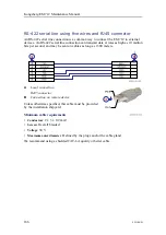
Page 186: ...cond and may be sent on cables as long as 1500 meters A Local connection RJ45 connector B Connection on remote device Unless otherwise specified this cable must be provided by the installation shipyard Minimum cable requirements Conductors 2 x 3 x 0 2 mm Screen Overall braided Voltage 30 V Maximum outer diameter Defined by the plugs and or the cable gland We recommend using a shielded CAT 6A quali...

Page 187: ...tor to the Processing Unit Two adapters and two standard Cat6 patch cables are provided with a standard delivery The adapter has RJ45 female connector at one end and 9 pin male D connector at the other end The wiring at the RJ45 side is fixed and the wire ends have crimp contacts to be placed in the desired position of the D connector without any tools A Local connection Processing Unit RJ45 conne...

Page 188: ...is equipped with a 1PPS signal input for clock synchronisation A Male BNC connector B Ground C 1PPS signal This cable must be provided by the installation shipyard The 1PPS one pulse per second signal is normally provided by a positioning system Kongsberg EM 712 Maintenance Manual ...

Page 189: ... is located on the CBMF board of the processing unit The connector is RJ45 type A Local connection The connector is RJ45 type Note Pin 3 and 6 is used by Kongsberg Maritime only B Connection on remote device Unless otherwise specified this cable must be provided by the installation shipyard Minimum cable requirements Conductors 2 x 3 x 0 2 mm Screen Overall braided Voltage 30 V Maximum outer diame...

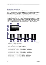
Page 190: ...Unit can be used to switch on off the Transmitter and Receiver Units in addition to the Processing Unit itself In this case the enclosed remote control dummy plug has to be inserted in the Remote Control connector in the Processing Unit A Remote switch and lamp optional B Processing Unit connector marked REMOTE CONTROL C Processing Unit connector marked 48VDC OUT D Transmitter Unit 1 connector mar...

Page 191: ...N OFF OUT Note The number of Transmitter Units and Receiver Units depends upon the chosen system configuration The diagram shows the principle for a maximum possible solution with two Transmitter Units and two Receiver Units Cable layout and interconnections ...

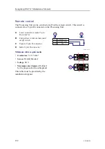
Page 192: ...nnection male 9 pin D connector B Connection to remote lamp and on off switch C Female 9 pin D connector D Male 9 pin D connector Minimum cable requirements Conductors 3 x 0 5 mm Screen Overall braided Voltage 60 V Maximum outer diameter Defined by the plugs and or the cable gland This cable must be provided by the installation shipyard Kongsberg EM 712 Maintenance Manual ...

Page 193: ... has been designed for this purpose K Rem A Local connection male 9 pin D connector B Connection at the terminal strip in Remote Control Unit K Rem C Female 9 pin D connector D Male 9 pin D connector Minimum cable requirements Conductors 3 x 0 5 mm Screen Overall braided Voltage 60 V Maximum outer diameter Defined by the plugs and or the cable gland This cable must be provided by the installation ...

Page 194: ... enclosed remote control dummy plug has to be inserted in the Remote Control connector in the Processing Unit Note If remote control is not used the enclosed remote control dummy plug has to be inserted in the Remote Control connector in the Processing Unit The Processing Unit will not work without this dummy plug Kongsberg EM 712 Maintenance Manual ...

Page 195: ...want to switch on and off the Transmitter Unit from the Processing Unit A Processing Unit end male 4 pin Lemo connector Lemo part number FGG 3B 304 CLAD62Z Kongsberg Maritime part number 348015 B Transmitter Unit end male 9 pin D connector Processing Unit end Pin layout male 4 pin Lemo connector Solder side view Connects to 48 VDC OUT on the rear of the Processing Unit Cable layout and interconnec...

Page 196: ...ON OFF IN on the RIO P board at the bottom of the Transmitter Unit Minimum cable requirements Conductors 2 x 0 5 mm Screen Overall braided Voltage 60 V Maximum outer diameter Defined by the plugs This cable must be provided by the installation shipyard Kongsberg EM 712 Maintenance Manual ...

Page 197: ...it and the Receiver Unit is required if you want to switch on and off the Receiver Unit from the Processing Unit A Transmitter Unit end male 9 pin D connector Connects to REMOTE ON OFF OUT at the bottom of the Transmitter Unit B Receiver Unit end male 9 pin D connector Connects to REMOTE ON OFF IN at the Receiver Unit Cable layout and interconnections ...

Page 198: ...198 451106 B Transmitter Unit end Pin layout male 9 pin D connector Connects to REMOTE ON OFF OUT on the RIO P board at the bottom of the Transmitter Unit Kongsberg EM 712 Maintenance Manual ...

Page 199: ...eiver Unit end Pin layout male 9 pin D connector Connects to REMOTE ON OFF IN at the Receiver Unit Minimum cable requirements Conductors 2 x 0 5 mm Screen Overall braided Voltage 60 V Cable layout and interconnections ...

Page 200: ...200 451106 B Maximum outer diameter Defined by the plugs This cable must be provided by the installation shipyard Kongsberg EM 712 Maintenance Manual ...

Page 201: ...veying and alignment page 202 Dimensional surveying page 202 Alignment page 203 Transducer array flatness page 203 Checking the transducer array flatness and correcting deviations page 204 Calibration page 205 Vessel coordinate system page 206 Dimensional surveying and alignment ...

Page 202: ...erfaces and prior to each survey Dimensional surveying Determining the relative positions and orientations of the sensors and the transducer with high accuracy is important This can only be met using a survey company personnel with good experience in maritime dimensional surveying The dimensional surveying tasks required for EM 712 include 1 Establishing the vessel coordinate system 2 Defining the...

Page 203: ...Alignment To ensure a successful installation of the EM 712 all alignment and measurements must be done to the highest possible accuracy The alignment tasks required for EM 712 include Measure and adjust the transducer frames to ensure that they have been mounted within the given tolerances Note Aligning the transducer for correct installation within the given tolerances requires professional skil...

Page 204: ...t possible accuracy The survey of the flatness can be carried out independently from the survey of the vessel coordinate system and alignment of the sensors Checking the transducer array flatness and correcting deviations An overall procedure specifying the main tasks is provided The detailed knowledge about how to do the measurements is offered by the consultants doing the work Prerequisites In s...

Page 205: ...he height differences 5 Verify that the mounting frame is in plane within the given tolerances 6 Repeat the procedure until the tolerances are met Calibration During the sea trials calibration surveys are required as described in the EM 712 end user documentation In order to check and verify the performance of the EM 712 system we strongly recommend that calibration surveys are done at regular int...

Page 206: ...their relative physical positions The antenna of a position sensor is typically mounted high above the superstructure while a motion sensor is often located close to the vessel s centre of gravity Both of these are physically positioned far away from the transducer on a depth sensor which may be located closer to the bow Very often the information from one sensor depends on data from an other It i...

Page 207: ...th the mast A positive value for Z means that a sensor or a new reference point is located under the reference point origin 4 Reference point Ship Origin Coordinate system origin The origin is the common reference point where all three axis in the vessel coordinate system meet All physical locations of the vessel s sensors radar and positioning system antennas echo sounder and sonar transducers mo...

Page 208: ...e box is used to describe all kinds of cases wooden or cardboard boxes etc used to hold the unit Topics Transporting Kongsberg Maritime equipment page 209 Lifting units and transportation boxes page 210 Inspection of units and transportation boxes after arrival page 212 Specifications for storage prior to installation or use page 213 Unpacking instructions page 215 Specifications for storage after...

Page 209: ...lations must be investigated by the packer shipper before the unit is dispatched Procedure 1 Ensure that all local transportation is done according to the same specifications as for the initial delivery 2 Make sure that the box containing the unit is kept dry at all times and sheltered from the weather It must not be subjected to shocks excessive vibration or other rough handling The box will norm...

Page 210: ...unit before you attempt to lift it 2 Make sure that you have the relevant lifting apparatus required and that this equipment is approved and certified for the load 3 If you need to use a crane a Check the applicable weight certificate for the crane b Check the security of the lifting lugs c If the unit to be lifted is provided with dedicated lifting lugs make sure that all available lugs are used ...

Page 211: ...106 B 211 Note Due to the nature of Kongsberg Maritime s products and the extensive use of delicate electronic parts all units and boxes must be regarded and handled as fragile equipment Equipment handling ...

Page 212: ... or other mishandling 2 If external damage is detected open the box to check its contents Request that a representative of the carrier to be present while the box is opened so any transportation damage can be identified and documented 3 If a unit has been damaged prepare an inspection report stating the condition of the unit and actions taken Describe the damage and collect photographic evidence i...

Page 213: ...s a If a unit is damaged prepare an inspection report stating the condition of the unit and the actions taken Describe the damage and collect photographic evidence if possible Re preserve the equipment b If the unit is not damaged check the humidity absorbing material If required dry or replace the bags then re pack the unit according to the packing instructions 7 If a box has been opened make sur...

Page 214: ...he box used to transport and store such units are clearly marked for example Must not be transported or stored in temperatures below 5 C Other temperature limits may be used if applicable If a unit needs temperature protection the box to be used for storage and transportation must be lined on all walls base and lid using minimum 5 cm thick polyurethane or polystyrene foam Most system units can nor...

Page 215: ...pped from Kongsberg Maritime Note If the unit in question is not unpacked for immediate use you may consider storing it unopened in its original box However it may be useful to open the box to check its contents for damage and retrieve any accompanying documentation Do not use a knife to open cardboard boxes the contents may be located close to the surface and can then be damaged by the blade Proc...

Page 216: ...the carton is open carefully remove all loose packing and insulation material 7 Check for user manuals and other documents that may have been added to the carton during packing 8 Check also for special tools door keys etc Unpacking mechanical units Prior to installation or use mechanical units must be unpacked from their transport boxes It is important that this unpacking is done without inflictin...

Page 217: ...circuit boards and other electronic units will always be wrapped in a clear plastic protective bag and the bag will be sealed Procedure 1 Lift the unit in its protective bag out of the transport box Note You must never use the cables to lift or carry a unit 2 Place it in a stable position on the floor or on the workbench 3 Inspect the unit for damage a If a unit has been damaged prepare an inspect...

Page 218: ...r must always be handled as a delicate instrument Incorrect actions may damage the transducer beyond repair Observe these transducer handling rules Do not activate the transducer when it is out of the water Do not lift the transducer by the cable Do not step on the transducer cable Do not handle the transducer roughly and avoid impacts Do not expose the transducer to direct sunlight or excessive h...

Page 219: ...451106 B 219 7 Observe the handling rules for transducers Equipment handling ...

Page 220: ...hese must then be reconnected during the installation procedure Units containing batteries are marked Caution Units containing lithium or alkaline batteries must be handled separately and with care Such units are marked accordingly Do not attempt to recharge such batteries open them or dispose of them by incineration Refer to the applicable product data sheets or battery handling procedures for fu...

Page 221: ...451106 B 221 Note Unless otherwise specified transducers and hydrophones must not be stored in temperatures below 10 C and above 50 C Equipment handling ...

Page 222: ...ST Built In Self Test introduction 23 BIST Built In Self test dialog box description 19 block diagram 12 book purpose 9 target audience 9 bottom panel description Transmitter Unit 89 95 brief description transducer 14 Built In Self Test CBMF test 25 CBMF CPU link 28 CPU test 24 introduction 23 RX channels 30 RX noise level 32 RX noise spectrum 33 RX Unit test 26 RX CBMF link 29 SW date and version...

Page 223: ...207 vessel 206 CPU board description 80 installing 51 removing 50 replacing 49 CPU Concurrent PP B12 spare part 67 CPU test BIST theory 24 D D connector to RJ45 Serial Line adapter 187 datagram format all 135 KMall 134 datagram formats depth information 136 gyro information 136 heading information 136 motion information 137 138 position information 135 138 depth information datagram formats 136 de...

Page 224: ...transportation boxes 210 storage after unpacking 220 storage prior to installation 213 transportation 209 unpacking 215 unpacking a hydrophone 218 unpacking a mechanical unit 216 unpacking a sonar head 218 unpacking a transducer 218 unpacking an electronic or electromechanical unit 217 visual inspection 212 Ethernet switch VadaTech CP218 spare part 70 Excelsys power supply spare part 67 70 externa...

Page 225: ... important transducer handling 36 information online 9 inspection transportation boxes 212 units 212 installation Processing Unit 48 installation requirements environmental 146 humidity 146 temperature 146 installing CBMF board 57 CPU board 51 fan unit 60 fuse Processing Unit 63 VadaTech CP219 Ethernet switch 54 instructions unpacking 215 interconnection cables list 164 interface specifications 13...

Page 226: ...tline dimensions drawing computer 124 Processing Unit 123 Receiver Unit 122 transducer 102 104 106 108 Transmitter Unit 120 Transmitter Unit mounting bracket 121 overview CBMF board 85 computer 16 99 Concurrent PP B12 CPU board 80 Concurrent PP833 CPU board 81 Hydrographic Work Station 16 99 Processing Unit 14 76 VadaTech CP219 Ethernet switch 83 P part number CBMF board 66 Concurrent PP B12 CPU b...

Page 227: ...6 storage temperature 146 weight 142 Prosessing Unit fuse installing 63 fuse removing 62 fuse replacement 61 PU front panel description 77 rear panel description 78 spare part 66 publication purpose 9 target audience 9 purpose CBMF board 85 computer 16 99 Concurrent PP B12 CPU board 80 Concurrent PP833 CPU board 81 Hydrographic Work Station 16 99 Processing Unit 14 76 this manual 9 VadaTech CP219 ...

Page 228: ...ternal synchronization 179 189 size display 143 Hydrographic Work Station 143 Hydrographic Work Station outline dimensions 124 rack installation kit 126 Remote Control Unit K Rem 127 technical specifications 142 transducer 142 sockets CBMF board 87 Concurrent PP B12 CPU board 81 Concurrent PP833 CPU board 82 VadaTech CP219 Ethernet switch 84 sonar head anti fouling paints 41 unpacking 218 spare pa...

Page 229: ...ansducer cable identification table 170 cable marking 168 Transmitter board LPTX36 spare part 69 Transmitter board TX RIO spare part 69 Transmitter Unit bottom panel description 89 95 brief description 15 89 cable plan 155 environmental specifications 146 outline dimensions drawing 120 power requirements 145 top panel description 91 weight and outline dimensions 143 Transmitter Unit mounting brack...

Page 230: ...12 W waterline alignment specifications 150 website download documents 9 weight display 143 Hydrographic Work Station 143 Processing Unit 142 RX Unit 143 technical specifications 142 transducer 142 TX Unit 143 wiring list of system interconnection cables 164 wiring diagram Hydrographic Work Station 163 Processing Unit 154 Receiver Unit 160 Remote Control Unit K Rem 129 topside 163 Transmitter Unit...

Page 231: ......

Page 232: ... 2019 Kongsberg Maritime ...

Reviews: