background image

OPERATION

OPERATION

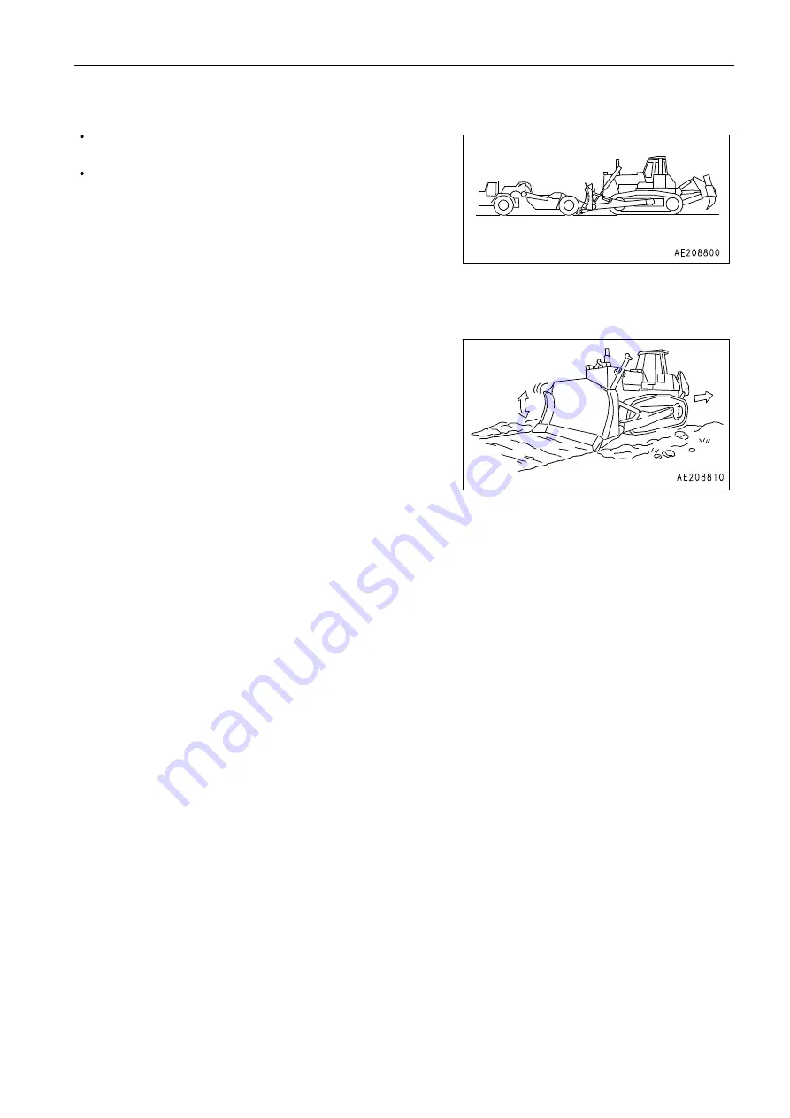
PUSHER OPERATIONS

When performing pusher operations, always install a pusher
plate.
When approaching the other machine, depress the decelerator
pedal to reduce the engine speed and approach slowly. After
coming into contact, raise the travel speed slowly and push with
full power.

SMOOTHING

NOTICE
Avoid smoothing on rocky or stony ground. It can damage the blade.

When finishing the ground surface to a smooth finish after digging or filling operations, keep a full load of soil in the
blade and operate the blade up or down in small movements while traveling forward. When leveling windrows or ruts
left by the tracks, set the blade to FLOAT position, travel at low speed in reverse and drag the blade over the ground
surface.

3 - 145

Summary of Contents for D475A-5E0

Page 1: ...cessary contact your local distributor for availability NOTICE Unsafe use of this machine may cause serious injury or death Operators and maintenance personnel must read this manual before operating or maintaining this machine This manual should be kept near the machine for reference and periodically reviewed by all personnel who will come into contact with it WARNING ...

Page 2: ... 1 1 ...

Page 3: ...elevant personnel can read it at any time Location to keep operation maintenance manual In door pocket inside of cab door If this manual is lost or damaged contact your distributor immediately to arrange for its replacement For details regardingthe machine serial No you will need to provide your Komatsu distributor see TABLE TO ENTER SERIAL NO AND DISTRIBUTOR PAGE 1 8 This manual uses the Internat...

Page 4: ...k of personal injury or death Follow the instructions in the safety message This signal word indicates an imminently hazardous situation which if not avoided will result in death or serious injury This signal word indicates a potentially hazardous situation which if not avoided could result in death or serious injury This signal word indicates a potentially hazardous situation exists which if not ...

Page 5: ...trees removing stumps Pushing Ripping For further details see WORK POSSIBLE USING BULLDOZER PAGE 3 144 and RIPPER OPERATION PAGE 3 151 FRONT REAR LEFT RIGHT DIRECTIONS OF MACHINE 1 A B Operator s seat Front Rear C D Left Right In this manual the terms front rear left and right refer to the travel direction as seen from the operator s seat when the operator s seat is facing the front 1 4 ...

Page 6: ...shows the area where the view is blocked by part of the machine when mirrors or other aids to visibility are installed as standard Be fully aware that there are places that cannot be seen when operating the machine 12M CIRCUMFERENCE VISIBILITY The visibility at a radius of 12 m 39 ft 4 in from the machine is as shown in the diagram below The hatched areas B show the areas where the view is blocked...

Page 7: ...llowing items PRODUCT IDENTIFICATION NUMBER PIN MACHINE SERIAL NO PLATE This is inside the console box on the left side of the operator s seat The design of the nameplate differs according to the territory ENGINE SERIAL NUMBER PLATE The normal nameplate is on the common rail cover at the bottom of the fuel prefilter on the left side of the engine 1 6 ...

Page 8: ...LADE SERIAL NO PLATE POSITION This is located on the upper right of blade back surface RIPPER SERIAL NO PLATE POSITION This is located on the left side surface of ripper beam POSITION OF SERVICE METER On top of the machine monitor 1 7 ...

Page 9: ... FOREWORD NECESSARY INFORMATION TABLE TO ENTER SERIAL NO AND DISTRIBUTOR Machine serial No Engine serial No Product identification number PIN Distributor name Address Service Personnel Phone Fax 1 8 ...

Page 10: ...ERATION 2 11 PREPARATIONS FOR SAFE OPERATION 2 11 FIRE PREVENTION 2 13 PRECAUTIONS WHEN GETTING ON OR OFF MACHINE 2 14 DO NOT GET CAUGHT IN WORK EQUIPMENT 2 16 PRECAUTIONS RELATED TO PROTECTIVE STRUCTURES 2 16 UNAUTHORIZED MODIFICATION 2 16 PRECAUTIONS RELATED TO ATTACHMENTS AND OPTIONS 2 16 PRECAUTIONS WHEN RUNNING ENGINE INSIDE BUILDING 2 17 PRECAUTIONS FOR OPERATION 2 18 PRECAUTIONS FOR JOBSITE...

Page 11: ...3 142 CHECK AFTER FINISHING WORK 3 143 LOCKING 3 143 WORK POSSIBLE USING BULLDOZER 3 144 EFFECTIVE USE OF MODE SELECTION SYSTEM 3 146 RIPPER OPERATION 3 151 OPERATING METHOD FOR RIPPING OPERATIONS 3 154 ADJUSTING POSTURE OF WORK EQUIPMENT 3 159 TIPS FOR LONGER UNDERCARRIAGE LIFE 3 162 TRANSPORTATION 3 164 TRANSPORTATION PROCEDURE 3 164 LOADING UNLOADING WORK 3 164 METHOD OF LIFTING MACHINE 3 167 T...

Page 12: ...CHART 4 19 SERVICE PROCEDURE 4 21 INITIAL 250 HOURS SERVICE ONLY AFTER THE FIRST 250 HOURS 4 21 WHEN REQUIRED 4 22 CHECK BEFORE STARTING 4 59 EVERY 250 HOURS SERVICE 4 60 EVERY 500 HOURS SERVICE 4 68 EVERY 1000 HOURS SERVICE 4 74 EVERY 2000 HOURS SERVICE 4 81 EVERY 4000 HOURS SERVICE 4 90 EVERY 8000 HOURS SERVICE 4 94 SPECIFICATIONS 5 1 SPECIFICATIONS 5 2 ATTACHMENTS OPTIONS 6 1 GENERAL PRECAUTION...

Page 13: ...29 MINING SPECIFICATION MACHINE 6 30 FRONT PANEL 6 30 SWITCH 6 31 FUSE BOX 6 37 CIRCUIT BREAKER FOR MAIN POWER SUPPLY 6 38 BATTERY ISOLATOR SWITCH STARTING MOTOR ISOLATOR SWITCH 6 39 TOOL BOX 6 39 CAR STEREO HANDLING 6 40 OPERATIONS AND CHECKS BEFORE STARTING ENGINE 6 41 STARTING WITH BOOSTER CABLES 6 42 CARRYING OUT KOWA Komatsu Oil Wear Analysis 6 43 WEAR PARTS 6 44 WHEN REQUIRED 6 46 EVERY 250 ...

Page 14: ... 2 1 ...

Page 15: ...2 PROVIDE FIRE EXTINGUISHER AND FIRST AID KIT 2 12 IF ANY PROBLEM IS FOUND 2 12 FIRE PREVENTION 2 13 ACTION IF FIRE OCCURS 2 13 PRECAUTIONS TO PREVENT FIRE 2 13 PRECAUTIONS WHEN GETTING ON OR OFF MACHINE 2 14 USE HANDRAILS AND STEPS WHEN GETTING ON OR OFF MACHINE 2 14 NO JUMPING ON OR OFF MACHINE 2 15 NO PEOPLE ON ATTACHMENTS 2 15 PRECAUTIONS WHEN STANDING UP FROM OPERATOR S SEAT 2 15 PRECAUTIONS ...

Page 16: ... AND MAINTENANCE BEFORE STARTING ENGINE 2 21 PRECAUTIONS WHEN STARTING ENGINE 2 21 PRECAUTIONS IN COLD AREAS 2 21 STARTING WITH BOOSTER CABLES 2 22 OPERATION 2 23 CHECKS BEFORE OPERATION 2 23 PRECAUTIONS WHEN TRAVELING IN FORWARD OR REVERSE 2 23 PRECAUTIONS WHEN TRAVELING 2 24 TRAVELING ON SLOPES 2 24 PRECAUTIONS WHEN OPERATING 2 25 PROHIBITED OPERATIONS 2 25 METHOD OF USING BRAKES 2 25 TRAVELING ...

Page 17: ...RKING UNDER MACHINE OR WORK EQUIPMENT 2 32 PROPER TOOLS 2 33 PRECAUTIONS FOR INSPECTION AND MAINTENANCE 2 34 PRECAUTIONS WHEN WELDING 2 34 HANDLING BATTERY 2 34 PRECAUTIONS WHEN USING HAMMER 2 35 PRECAUTIONS WITH HIGH TEMPERATURE COOLANT 2 35 PRECAUTIONS WITH HIGH TEMPERATURE OIL 2 35 PRECAUTIONS WITH HIGH PRESSURE OIL 2 36 PRECAUTIONS WITH HIGH PRESSURE FUEL 2 36 HANDLING HIGH PRESSURE HOSES AND ...

Page 18: ...ways keep them clean When cleaning them do not use organic solvents or gasoline These may cause the labels to peel off If the labels are damaged lost or cannot be read properly replace them with new ones For details of the part numbers for the labels see this manual or the actual label and place an order with Komatsu distributor There are also other labels in addition to the warning signs and safe...

Page 19: ... SAFETY SAFETY LABELS SAFETY LABELS 1 Caution before operating machine 09651 A0641 2 Caution before moving in reverse 09802 B0750 3 Caution for leaving operator s seat 09654 B0641 2 6 ...

Page 20: ...ETY LABELS 4 Caution for hot water hazard 09653 A0481 5 Caution for hot oil hazard 09653 A0481 6 Caution for adjusting track tension 195 98 22931 Safety label is attached to the back side of the inspection cover of the track frame 2 7 ...

Page 21: ... SAFETY SAFETY LABELS SAFETY SAFETY LABELS 7 Caution for battery cable 09808 A0881 8 Caution when engine running 09667 A0481 9 Caution when handling accumulator 09659 A057B 2 8 ...

Page 22: ...LS 10 Caution for approach when machine moving 09806 B1683 11 Caution for ROPS 09620 B2000 12 Caution for FOPS 09620 C2000 13 Caution about high pressure for common rail 6217 71 9331 14 Prohibited to start by short circuiting 09842 A0481 2 9 ...

Page 23: ... SAFETY SAFETY LABELS SAFETY SAFETY LABELS 15 Caution for blast site 09845 00480 only when equipped with KOMTRAX Plus 2 10 ...

Page 24: ...oughly If there are any places in this manual that you do not understand ask the person in charge of safety to give an explanation PREPARATIONS FOR SAFE OPERATION PRECAUTIONS REGARDING SAFETY RELATED EQUIPMENT Be sure that all guards covers and mirrors are in their proper position Have guards and covers repaired immediately if they are damaged Understand the method of use of safety features and us...

Page 25: ...struct operation and cause the machine to move unexpectedly resulting in serious personal injury or death Do not stick suction pads to the window glass Suction pads act as a lens and may cause fire Do not use a cell phone when driving or operating the machine This may lead to mistakes in operation which could cause serious personal injury or death Never bring any dangerous objects such as flammabl...

Page 26: ... diesel oil or gasoline There is danger that they may catch fire Do not weld or use a cutting torch to cut any pipes or tubes that contain flammable liquids Determine well ventilated areas for storing oil and fuel Keep the oil and fuel in the determined place and do not allow unauthorized persons to enter When performing grinding or welding work on the machine move any flammable materials to a saf...

Page 27: ... Use the parts marked by arrow A in the diagrams when getting on or off the machine Never use the parts marked by arrow B when getting on or off the machine Use them only when moving along the top of the track or when checking or performing maintenance inside the side cover or when filling the tank with oil Always face the machine and maintain at least 3 point contact both feet and one hand or bot...

Page 28: ...op the engine If you accidentally touch the levers when they are not locked there is a hazard that the machine may suddenly move and cause serious injury or property damage PRECAUTIONS WHEN LEAVING MACHINE If the proper procedures are not taken when parking the machine the machine may suddenly move off by itself and this may lead to serious personal injury or death Always observe the following Whe...

Page 29: ...d or holes are drilled in it or it is modified in any other way its strength may drop Any modification is prohibited If the protective structure is damaged or deformed by falling objects or by rolling over its strength will be reduced and it will not be able to fulfill its function properly In such cases always consult your Komatsu distributor Even if the protective structure is installed always f...

Page 30: ...ns substances that may damage your health or even cause death Start or operate the engine in a place where there is good ventilation If the engine or machine must be operated inside a building or under ground where the ventilation is poor take steps to ensure that the engine exhaust gas is removed and that ample fresh air is brought in 2 17 ...

Page 31: ... any unauthorized person from entering the operating area In particular if you need to operate on a road protect pedestrian and cars by designating a person for worksite traffic duty or by installing fences around the worksite When traveling or operating in water or on soft ground check the water depth speed of the current bedrock and shape of the ground beforehand and avoid any place that will ob...

Page 32: ...the machine approaches too close to the electric cables When performing operations near high voltage cables do not let anyone near the machine If the machine should come too close or touch the electric cable to prevent electric shock the operator should not leave the operator s compartment until it has been confirmed that the electricity has been shut off Also do not let anyone near the machine EN...

Page 33: ...here is danger that there may be asbestos dust in the air always operate the machine from an upwind position and make sure that all workers operate on the upwind side All workers should use anti dust masks Do not allow other persons to approach during the operation Always observe the rules and regulations for the work site and environmental standards This machine does not use asbestos but there is...

Page 34: ...ror and check that the control levers are all at NEUTRAL position Before starting the engine check that work equipment lock lever 1 and parking brake lever 2 are in LOCK position L Adjust the mirrors so that you can get a good rearview from the operator s seat For the details of adjustment see ADJUST MIRROR PAGE 3 109 Check that there are no persons or obstacles above below or in the area around t...

Page 35: ... the operator s seat and the other working with the battery When starting from another machine do not allow the nomal machine and failed machine When connecting the booster cables turn the starting switch to OFF position for both the normal machine and failed machine There is a hazard that the machine will move when the power is connected Be sure to connect the positive cable first when installing...

Page 36: ...ere is no leakage of oil or fuel If any problem is found perform repairs immediately PRECAUTIONS WHEN TRAVELING IN FORWARD OR REVERSE Lock the cab door and windows securely both when they are open and when they are closed Do not allow anyone apart from the operator to ride on the machine If there are any persons in the area around the machine there is danger that they may be hit or caught by the m...

Page 37: ...r The work equipment may hit the ground surface and cause the machine to lose its balance or may damage the machine or structures in the area When passing over bridges or structures check first that the structure is strong enough to support the weight of the machine When operating in tunnels under bridges under electric wires or other places where the height is limited operate slowly and be extrem...

Page 38: ... pedal the brake will always be applied and this will cause the brakes to overheat and fail Do not depress the brake pedal repeatedly if not necessary When traveling downhill use the braking force of the engine TRAVELING ON SNOW COVERED OR FROZEN SURFACES Snow covered or frozen surfaces are slippery so be extremely careful when traveling or operating the machine and do not operate the levers sudde...

Page 39: ...ver 2 to LOCK position L and stop the engine Always close the operator s cab door and use the key to lock all the equipment in order to prevent any unauthorized person from moving the machine Always remove the key take it with you and leave it in the specified place If it is necessary to park the machine on a slope always observe the following Set the work equipment on the downhill side and dig it...

Page 40: ...h Be sure that the ramps are wide long and thick enough to provide a safe loading slope Take suitable steps to prevent the ramps from moving out of position or coming off Be sure the ramp surface is clean and free of grease oil ice and water Remove dirt from the undercarriage On a rainy day in particular be extremely careful since the ramp surface is slippery Run the engine at Low idle MIN and dri...

Page 41: ...see METHOD OF TOWING MACHINE PAGE 3 178 Always confirm that the wire rope or drawbar used for towing has ample strength for the weight of the machine being towed Never use a wire rope which has cut strands A reduced diameter B or kinks C There is danger that the rope may break during the towing operation Always wear leather gloves when handling wire rope Never tow a machine on a slope During the t...

Page 42: ...rning tag part number 09963 A1640 When not using this warning tag keep it in the toolbox If there is no toolbox keep it in the pocket for the Operation and Maintenance Manual KEEP WORKPLACE CLEAN AND TIDY Do not leave hammers or other tools lying around in the work place Wipe up all grease oil or other substances that will cause you to slip Always keep the work place clean the tidy to enable you t...

Page 43: ...r to RAISE and LOWER position 2 or 3 times repeatedly to release the remaining pressure in the hydraulic circuit then set parking brake lever 1 and work equipment lock lever 2 to LOCK position L Check that the battery relay is off and main power is not conducted Wait for approximately 1 minute after turning off the engine starting switch key and press the horn switch If the horn does not sound it ...

Page 44: ...eful not to come close Never drop or insert tools or other objects into the fan fan belt or other rotating parts There is danger that they may contact the rotating parts and break or be sent flying Set work equipment lock lever 1 and parking brake lever 2 to LOCK position L to prevent the work equipment from moving Do not touch any control levers If any control lever must be operated give a signal...

Page 45: ...s you use are in good repair and strong enough to handle the weight of the component Never use hydraulic jacks at places where the machine is damaged bent or twisted Never use if the element wire of wire rope is frayed twisted or pinched Never use bent or distorted hooks It is extremely dangerous to work under the machine if the track shoes are lifted off the ground and the machine is supported on...

Page 46: ...MAINTENANCE PROPER TOOLS Use only tools suited to the task and be sure to use the tools correctly Using damaged deformed or low quality tools or making improper use of the tools may cause serious personal injury or death 2 33 ...

Page 47: ...wipe to clean the battery A wet wipe will prevent fire or explosion from static electricity Do not smoke or bring any open flame close to the battery Hydrogen gas is generated when the battery is being charged so remove the battery from the machine take it to a well ventilated place remove the battery caps then perform the charging After charging tighten the battery caps securely Danger from dilut...

Page 48: ...dingarea If hard metal parts such as pins bucket teeth cutting edges or bearings are hit with a hammer there is a hazard that pieces might be scattered and cause serious personal injury or death Always wear protective eyeglasses and gloves If the pin is hit with strong force there is a hazard that it may fly out and injure people in the surrounding area Do not allow anyone to enter the surrounding...

Page 49: ...jury to your skin or eyes wash the place with clean water and consult a doctor immediately for medical attention PRECAUTIONS WITH HIGH PRESSURE FUEL When the engine is running high pressure is generated in the engine fuel piping When performing inspection or maintenance of the fuel piping system stop the engine and wait for at least 30 seconds to allow the internal pressure to go down before start...

Page 50: ...ck tension never loosen it more than one turn In doing so loosen the valve slowly Never put your face hands feet or any other part of your body directly in front of grease drain valve 1 DO NOT DISASSEMBLE RECOIL SPRING Never disassemble the recoil spring assembly The recoil spring assembly has a powerful spring that acts to reduce the impact on the idler If it is disassembled by mistake the spring...

Page 51: ...d air there is a hazard of serious personal injury or death caused by flying dust or particles When using compressed air to clean the filter element or radiator wear protective eyeglasses anti dust mask gloves and other protective equipment MAINTENANCE OF AIR CONDITIONER If air conditioner refrigerant gets into your eyes it may cause loss of sight if it contacts your skin it may cause frostbite Ne...

Page 52: ...CEMENT OF SAFETY CRITICAL PARTS PAGE 4 16 The material of these components naturally changes over time and repeated use causes deterioration wear and fatigue As a result there is a hazard that these components may fail and cause serious personal injury or death It is difficult to judge the remaining life of these components from external inspection or the feeling when operating so always replace t...

Page 53: ... ...

Page 54: ... 3 1 ...

Page 55: ... OPERATION GENERAL VIEW GENERAL VIEW GENERAL VIEW OF MACHINE 1 2 3 4 5 Blade Blade lift cylinder Cab Fuel tank Ripper 6 7 8 9 10 Sprocket Track frame Frame Track shoe ROPS 3 2 ...

Page 56: ... switch Rear lamp switch Fan rotation selector switch Air conditioner panel or heater panel Display panel A speed range display engine speed Auto shift down switch 12 13 14 15 16 17 18 19 20 21 22 23 Starting switch Information switch Buzzer cancel switch Brake pedal Deceleration pedal Blade control lever Horn switch Wiper switch Room lamp switch Extra strong wind flow switch Additional heater swi...

Page 57: ...Engine coolant temperature caution lamp Power train oil temperature caution lamp Hydraulic oil temperature caution lamp 13 14 15 16 17 18 19 20 21 22 23 24 25 Air cleaner clogging caution lamp Engine pre heating pilot lamp Maintenance caution lamp Dual single tilt selector display lamp Warning lamp Fan rotation selection impossibility lamp Hydraulic oil level caution lamp if equipped Engine oil le...

Page 58: ...machine To perform suitable operations correctly and safely it is important to completely understand methods of operating the equipment and the meanings of the displays FRONT PANEL A B C D Emergency caution items Caution monitor group Check monitor group Meter and indicator group E F G Mode selection switch group Switches Lamps 3 5 ...

Page 59: ...o ON If any monitor lamp does not light have your Komatsu distributor inspect and repair it These items need to be observed while the engine is running If any abnormality occurs items that need to be repaired immediately are displayed If there is any abnormality alarm buzzer sounds intermittently and the abnormal location on the caution lamp will flash 1 2 3 Engine oil pressure caution lamp Engine...

Page 60: ...e in the coolant temperature When the monitor lamp flashes run the engine at low idle speed until green range of the engine coolant temperature gauge lights up POWER TRAIN OIL TEMPERATURE CAUTION LAMP Lamp 3 warns operator that the torque converter outlet port oil temperature has risen If it flashes run the engine at low idle until the power train oil temperature gauge goes down to the green range...

Page 61: ...DRAULIC OIL LEVEL CAUTION LAMP if equipped This lamp 5 warns the operator that the level of the hydraulic oil in the hydraulic tank has gone down If the lamp flashes check the level of the hydraulic oil in the hydraulic tank and add oil 3 8 ...

Page 62: ...engine is running If any problem occurs the item needing immediate repair is displayed If there is any problem the problem location on the caution lamp will flash 1 2 Charge condition caution lamp Maintenance caution lamp 3 Air cleaner clogging caution lamp CHARGE CONDITION CAUTION LAMP Lamp 1 indicates an abnormality in the charging system while the engine is running If the monitor lamp flashes c...

Page 63: ...hange interval has been reached DISPLAY PANEL B Multi information PAGE 3 17 to the maintenance mode and check or replace the applicable filter or oil AIR CLEANER CLOGGING CAUTION LAMP Lamp 3 warns operator that the air cleaner is clogged If it flashes stop the engine check and clean the air cleaner 3 10 ...

Page 64: ... and repair REMARK When the starting switch is turned to ON position before starting the engine the caution lamps flash for 3 seconds the warning lamps light up for 3 seconds and the alarm buzzer sounds for 1 second The caution lamps cannot be checked for any malfunction until at least 5 seconds after the engine has been stopped This displays the basic items among the check before starting items t...

Page 65: ...ater ENGINE OIL LEVEL MONITOR if equipped This lamp 2 warns the operator that the level of the engine oil in the engine oil pan has gone down If the lamp flashes check the oil level in the engine oil pan and add oil HYDRAULIC OIL LEVEL CAUTION LAMP if equipped This lamp 3 warns the operator that the level of the hydraulic oil in the hydraulic tank has gone down If the lamp flashes check the level ...

Page 66: ...all light up If they do not have your Komatsu distributor inspect and repair it 1 2 3 4 5 6 Engine coolant temperature gauge Power train oil temperature gauge Hydraulic oil temperature gauge Fuel level gauge Engine pre heating pilot lamp Dual single tilt selector display lamp dual tiltdozer specification 7 8 9 Torque converter lock up display indicator Display panel A speed range display engine sp...

Page 67: ...e gauge often enters red range C check the radiator for clogging POWER TRAIN OIL TEMPERATURE GAUGE Gauge 2 indicates the torque converter outlet oil temperature If the temperature is normal during operation green range B will light If red range C lights up during operation move the fuel control dial to lower engine speed to approximately 3 4 of High idle MAX reduce the load and run until the oil t...

Page 68: ...nge Green range Red range FUEL LEVEL GAUGE Gauge 4 fuel level in the fuel tank During normal operation the green range B should be lit If red range A lights up during operation add fuel immediately If this is not done the engine speed will become irrgular or an error display will be shown on the monitor A B Red range Green range REMARK The display is not proportional to the amount of fuel remainin...

Page 69: ...irect drive after lock up switch for the mode selection switch panel has been turned ON The lamp goes out when torque converter drive is being used DISPLAY PANEL A speed range display engine speed Meter 8 displays transmission speed range B being used on the machine and engine speed When the transmission is in 1st FORWARD the display shows F1 and when it is in 1st REVERSE the display shows R1 The ...

Page 70: ...r The total operating hours of the machine is displayed at the bottom right of the monitor Use the service meter function display to set the interval for periodic maintenance When the engine is running the service meter advances even if the machine is not moving When the engine is running the hourglass mark pilot display at the side of the meter lights up to show that the meter is advancing The me...

Page 71: ...erse slow mode can be selected in combination with the lock up mode The economy mode and reverse slow mode can be used independently or in combination 1 2 Lock up mode switch Economy mode switch 3 Reverse slow mode selector switch Selecting mode to match the type of work and quality of rock and soil makes to perform operations effectively Dozing Reverse slow mode Lock up mode Economy mode Possible...

Page 72: ...n it is ON the lamp lights up ECONOMY MODE SWITCH Switch 2 is used for hauling work after ripping or for dozing blasted rock When the system is OFF if the switch is pressed once mode 1 lights up and if it is pressed again mode 2 lights up Select the mode according to the type of rock REVERSE SLOW MODE SELECTOR SWITCH Switch 3 is used to make small reductions in the travel speed when traveling in R...

Page 73: ... 1 2 3 4 5 Starting switch Buzzer cancel switch Front lamp working lamp switch Rear lamp switch Fan rotation selector switch 6 7 8 9 Auto shift down switch Information switch Extra strong wind flow switch Additional heater switch if equipped 3 20 ...

Page 74: ...ng the engine Set the key to this position while cranking initial rotation of starting motor and after starting the engine put your hand off from the key immediately The key will return to ON position B BUZZER CANCEL SWITCH When switch 2 is operated to the left or right the alarm buzzer stops When the information monitor is in the maintenance mode switch 2 can be operated to move the curser left o...

Page 75: ... switch key to OFF position to make sure that the engine is not running REMARK The cooling fan rotation selector switch does not work when it is operated while the engine is running In that case the fan rotation selection impossibility lamp flashes to indicate that the fan rotation cannot be changed The cooling fan rotation selector switch returns to the normal mode when the engine stops or when t...

Page 76: ... the maintenance mode a position Cursor moves to left c position Cursor moves to right EXTRA STRONG WIND FLOW SWITCH Switch 8 is used to provide a stronger wind flow than fo the normal HIGH position ADDITIONAL HEATER SWITCH if equipped Switch 9 actuates the hot water heater Position a Hot water heater OFF Position b Hot water heater LOW ON Position c Hot water heater HIGH ON 3 23 ...

Page 77: ... OPERATION EXPLANATION OF COMPONENTS LAMPS 1 2 Warning lamp Fan reversal lamp 3 Fan rotation selection impossibility lamp 3 24 ...

Page 78: ...ure code is displayed carry out the remedy given in OTHER TROUBLE PAGE 3 184 If the lamp flashes check the monitor panel to locate the abnormality When the monitor inside the CAUTION A group flashes the alarm buzzer also sounds continuously See FRONT PANEL PAGE 3 5 FAN REVERSAL LAMP This lamp 2 lights up when the clean mode is selected FAN ROTATION SELECTION IMPOSSIBILITY LAMP Orange This lamp 3 l...

Page 79: ...3 32 Each mode is operated by using information switch 2 and buzzer cancel switch 3 on the dashboard in front of the operator s seat After operating the switch release the switch and the switch will return automatically to the center position as shown in the diagram on the right The functions of each position of the switches are as follows Moves mode to left Moves mode to right Selects mode Cancel...

Page 80: ...isplay mode position Go to maintenance mode position Go to normal operation screen position Go to PM clinic auxiliary mode selection item screen 3 The diagram on the right shows the screen display for the fault code display mode Use the controls to change the mode as follows position Go to adjustment mode position Go to PM clinic auxiliary mode position Go to normal operation screen position Go to...

Page 81: ...f times that replacement has been made until now is displayed The display items can be displayed in order by operating the information switch to the left or right Display Item 1st replacement interval 2nd and following replacement intervals 1 01 ENG OIL Engine oil 500h 500h 2 02 ENG FLT Engine oil filter 500h 500h 3 03 FUEL FLT Fuel filter 1000h 1000h 4 04 HYD FLT Hydraulic oil filter 250h 2000h 4...

Page 82: ... Operate the information switch to select YES then operate the buzzer cancel switch to The replacement account will increase by 1 the replacement interval will be reset and the oil filter change interval lamp will go out When this is done if the maintenance caution lamp does not go out there is another item close to the replacement time so check the situation REMARK To return to the function selec...

Page 83: ...ine coolant temperature temperature C 03 ENG OIL PRESS Engine oil pressure Pressure kPa 04 AMB PRESS Ambient pressure Pressure kPa 05 BOOST PRESS Engine boost pressure Pressure kPa 06 BOOST TEMP Engine boost temperature temperature C 07 T C TEMP Torque converter oil temperature temperature C 08 HYD TEMP Hydraulic oil temperature temperature C 09 HYD PUMN PRES F Hydraulic oil pressure F pump Pressu...

Page 84: ...tected the location and fault code are displayed by a 6 digit code on display panel B When contacting your Komatsu distributor inform your distributor of the code at the same time If the failure observation function has not determined the condition of the machine the display is as shown in the diagram on the right With this function existing failures can be displayed up to a maximum of 20 items If...

Page 85: ...l On this screen operate the buzzer cancel switch to to switch to the screen to adjust the brightness The brightness can be adjusted by operating the information switch The higher the number the brighter the screen becomes the lower the number the darker the screen becomes position Number increases position Number decreases When the buzzer cancel switch is operated to the brightness of the liquid ...

Page 86: ...hting is set 3 Adjusting contrast of liquid crystal message display The diagram on the right is the mode for adjusting the contrast of the liquid crystal message display On this screen operate the buzzer cancel switch to to switch to the screen to adjust the contrast The contrast can be adjusted by operating the information switch The higher the number the darker the screen becomes the lower the n...

Page 87: ...he diagram on the right shows the mode for machines equippedwith prelube Contact your Komatsu distributorwhen using this function The diagram on the right shows the mode for emergency starting when there is a failure in the prelube equipment For machines equipped with prelube When the monitor shows this screen and the information switch is turned the bottom line of the display is turned OFF In thi...

Page 88: ...witch Room lamp switch Wiper switch Cigarette lighter 5 6 7 Accessory socket Connector for VHMS download Connector for VHMS download HORN SWITCH The horn sounds when button 1 at rear of the blade control lever on the right side of operator s seat is pressed 3 35 ...

Page 89: ... are as follows A L H door B Front window C R H door D Rear window On machines with the double wiper specification operate the switches on left door A and right door C to operate the wipers at the top and bottom of the door simultaneously This is also used as the window washer switch The switch is operated as follows Window washer only Keep the switch pressed to OFF position to spray out water 3 3...

Page 90: ... sprayed out REMARK When installing the cab check the colors of the washer tank and window washer hoses and be sure to connect correctly a Front of machine b Front no color c Rear black d Left side blue e Right side red No Name Content 1 Washer tube Red Right door Blue Left door Black Rear window No color Front window 2 Power source of cab 5R ACC power source of cab 2R Backup power source 3 4 pole...

Page 91: ...e equipment The capacity of the cigarette lighter is 120 W 24 V x 5 A ACCESSORY SOCKET Socket 5 is used as the power source for a wireless device or other 12 V equipment With both Type A and Type B electricity flows only when the ignition switch is at ON position The capacity for both Types A and B is 60 W 12 V x 5 A REMARK This socket is under the left armrest CONNECTOR FOR VHMS DOWNLOAD It is po...

Page 92: ...ONENTS ADDITIONAL WORKING LAMP SWITCH OPTION SWITCHES These switches are used respectively for the following additional lamps and rotating lamp E e Additional front lamp switch F f Additional rear lamp switch G g Rotating lamp 3 39 ...

Page 93: ...al 5 6 7 8 9 Parking brake lever Work equipment lock lever Brade control lever Ripper control lever Pin puller control switch FUEL CONTROL DIAL Dial 1 is used to control the engine speed and output a Low idle MIN position Turn fully to the left b High idle MAX position Turn fully to the right REMARK To stop the engine turn the starting switch to OFF position 3 40 ...

Page 94: ...n steering the machine the lever will return to the a position or the b position and the machine will be returned to straight movement Gear shifting When the joystick is at FORWARD or REVERSE position and switch c or switch d is pushed the transmission speed will change UP switch c Each time the switch is pressed the transmission will shift up one speed DOWN switch d Each time the switch is presse...

Page 95: ...soil from a cliff the load on the machine will suddenly be reduced and the travel speed will increase This situation is dangerous so use the decelerator pedal to reduce the travel speed of the machine Pedal 4 is used when reducing engine speed or stopping the machine When switching between forward and reverse or when stopping the machine use this pedal to reduce speed REMARK When operating the dec...

Page 96: ...e the work equipment lock lever securely to LOCK position If the blade control and ripper control levers are not locked and are touched by accident it may lead to serious injury or damage If the work equipment lock lever is not completely in LOCK position L the lock may not be applied Check that it is in the position shown in the diagram When parking the machine or when performing maintenance alwa...

Page 97: ... control a RAISE b HOLD Blade is stopped and held in this position c LOWER d FLOAT Blade will move freely according to external force REMARK When released from FLOAT position this lever 7 will not return to HOLD position so it must be returned to HOLD by hand Tilting control A RIGHT TILT B LEFT TILT REMARK With the tilt operation the blade can be operated to RAISE HOLD or LOWER 3 44 ...

Page 98: ...ing control a RAISE b HOLD Blade is stopped and held in this position c LOWER d FLOAT Blade will move freely according to external force REMARK When released from FLOAT position this lever 7 will not return to HOLD position so it must be returned to HOLD by hand Single tilt operation Operate the tilt switch 1 to the C position A RIGHT TILT B LEFT TILT 3 45 ...

Page 99: ...rform operation B with the pitch button 2 pressed Forward pitch F cutting angle increased Perform operation A with the pitch button 2 pressed REMARK With the pitch operation the blade can be operated to any of RAISE HOLD or LOWER For details of the effective use of the dual tiltdozer see EFFECTIVE METHOD OF OPERATION FOR DUAL TILTDOZER PAGE 6 13 To operate the pitch keep the pitch button pressed a...

Page 100: ...ble ripper Lever 8 is used to operate the ripper Lifting control a RAISE b HOLD Ripper is stopped and held in the same position c LOWER Tilting control A Digging angle reduced Cutting angle α becomes smaller B Digging angle increased Cutting angle α becomes larger 3 47 ...

Page 101: ...the optimum position 3 Tighten lock bolt 1 with the wrench to hold lever 2 in position Adjustment within range of 40 mm 1 6 in from neutral to front 1 Remove lock bolt 1 with a wrench 2 Remove lever 2 and reverse it 180 deg 3 Install lever 2 to lever 5 then set it to the optimum position 4 Tighten lock bolt 1 with the wrench to hold lever 2 in position 5 Loosen nut 3 6 Reverse knob 180 deg 7 Tight...

Page 102: ...IR CLEANER ELEMENT PAGE 4 25 POWER SOURCE The cigarette lighter socket 1 can be used as a power source for 24 V equipment and the accessory socket 2 can be used for 12 V equipment NOTICE The cigarette lighter is 24 V Do not use it as the power source for 12 V equipment The capacity of the cigarette lighter is 120 W 24 V x 5 A There are 2 accessory sockets Their capacity is 60 W 12 V x 5 A These 2 ...

Page 103: ...es corroded or is covered in white powder or if there is any looseness between the fuse holder and the fuse Always replace the fuse with a fuse of the specified capacity Chassis Open the fuse inspection cover A at the bottom front left of the operator s compartment Fuse box is installed inside Fuse box 1 Fuse box 2 Fuse box 3 Cab machines equipped with cab Fuse box 4 is installed at the bottom of ...

Page 104: ...heater power source pin puller air suspension seat 3 20 A Additional heater power source 4 20 A Working lamp 5 20 A Rear lamp Fuse box 3 NO Fuse capacity Name of circuit 1 5 A ACC signal 2 20 A Horn 3 20 A Spare power source 1 4 20 A Spare power source 2 5 20 A Spare ACC signal Fuse box 4 NO Fuse capacity Name of circuit 1 10 A Car radio cigarette lighter room lamp 2 10 A Rear wiper 3 10 A R H wip...

Page 105: ... normal reset button 1 will stay pushed in If it comes out immediately when it is pushed in the electric circuit must be checked No Capacity Circuit 1 20 A Steering controller 2 20 A Monitor panel 3 20 A Transmission controller 4 20 A Air con main power 5 20 A Head lamp 6 20 A Starter switch REMARK The circuit breaker is a device installed in electric circuits where a large current flows It is ins...

Page 106: ... shut off the operation of the reset button is heavier than when the circuit is normal The height of the reset button is the same regardless of whether the circuit has been shut off or has been reset so make note of the effort of the reset button when resetting the circuit Do not keep the circuit breaker reset button longer than necessary If the starting motor does not work even when the circuit b...

Page 107: ...or locked open securely The door may swing closed because of the vibration SASH GLASS INTERMEDIATE LOCK When working with the cab sash glass open use this lock to prevent the glass from chattering When the lever is in FREE position F the glass can be opened or closed When the lever is moved to LOCK up or down position the glass is fixed in position If the glass is not held securely set the lever i...

Page 108: ...hod of opening or closing the locks on the caps are as follows OPENING THE COVER 1 Insert the key Make sure that you have inserted the key fully 1 before turning it If the key is turned when only partially inserted it may break L LOCK position F OPEN position A working angle of key 180 deg B 45 deg 2 Turn the key counterclockwise to align the match mark 2 on the cap with the rotor groove then turn...

Page 109: ...e stopper and the cap can be opened CLOSING THE CAP 1 After turning lever 1 in the c direction counterclockwise keep it in that position and fit the cap 2 Turn lever 1 in the d direction clockwise until it stops at the stopper and then tilt it in the b direction DOOR POCKET This is inside the left and right doors Use it for keeping things Do not put the heavy tools or other heavy objects in it If ...

Page 110: ...tinguish the cigarette before closing the lid TOOL BOX Toolbox is located inside of the left fender CLEAN INTERIOR OF CAB If there is any oil or dirt stuck to cab interior 1 and 2 apply a neutral detergent to a cloth and dab to remove the dirt then wash with water After washing with water dry completely and assemble 3 57 ...

Page 111: ...udness button Time radio display selector button Tape eject button 8 9 10 11 12 13 14 Cassette door Fast forward rewind buttons Preset buttons Metal tape button Manual tuning buttons Seek tuning buttons Band selector button A B C D Band display Metal tape display FM stereo reception display Loudness display E F G Tape direction display Preset channel display Time frequency display 3 58 ...

Page 112: ... search for the desired station within a receivable band and memorize the frequency in the preset memory During this scanning process the frequency shown in the right side of display continues to change This indicates that each frequency is memorized in the auto store REMARK The auto store function cannot be used when the channel display is flashing When the display is flashing the preset scan fun...

Page 113: ... hear more easily by emphasizing the low tone when the low tones are weak Push button Actuated ON Push button again Canceled OFF TIME RADIO DISPLAY SELECTOR BUTTON This button 6 is used to switch between Radio tape display and Time display Correcting time Press the button to set to the time display A Correcting hour Keep the DISP button pressed and press the bottom tuning button H to correct the h...

Page 114: ...ard or rewind the tape Fast forward rewind If you press the button pointing in the same direction as the arrow indicating the direction of play the tape will be fast forwarded if you press the button pointing in the opposite direction the tape will be rewound To stop the tape lightly press the button that is not locked The fast forward or rewind operation will be canceled PRESET BUTTONS These butt...

Page 115: ...1 MHz for FM when button is pressed the frequency goes down 9 kHz for AM or 0 1 MHz for FM If the button is pressed down and held the frequency will change continuously SEEK TUNING BUTTONS These buttons 13 are used to seek tuning When SEEK UP button is pressed the search automatically goes up when SEEK DN button is pressed the search automatically goes down When the next station that can be receiv...

Page 116: ...on 1 to select MW AM FM1 or FM2 then use the manual tuning button to select the frequency of the broadcasting station 3 Press manual memory button 2 or seek tuning button 3 4 Press preset button 4 of the number to be preset for 2 seconds while the frequency display is being shown on the display The preset channel and frequency are displayed and the presetting is completed 5 Repeat steps 2 to 4 to ...

Page 117: ...IO 1 Turn the starting switch ON then turn power switch 1 ON 2 Set band selector button 2 to AM or FM 3 Select the station with the preset buttons or manual tuning button 3 4 Adjust the volume balance and tone as desired 5 When turning the radio OFF turn power switch 1 to the left until it clicks REMARK To switch to the radio when listening to a cassette press the cassette eject button to stop the...

Page 118: ...ay is pointing to the right the top side is being played if the arrow is pointing to the left the bottom side is being played When the tape reaches the end it is automatically reversed and the other side starts to play 3 When finished with the tape press the cassette eject button to eject the tape and automatically switch to the radio REVERSING TAPE When listening to the tape press both FAST FORWA...

Page 119: ...t to let water get in these items Do not wipe the scales or buttons with solvent such as benzene or thinner Wipe with a dry soft cloth If the dirt cannot be removed easily soak the cloth with alcohol If the battery is disconnected such as when it is being replaced the settings for the preset buttons stored in memory may all be deleted so reset them after reconnecting the battery NOTICE Handling ca...

Page 120: ...operator s seat The vents blow out cool air or hot air to cool or heat the cab Location of vents A Rear vent B Front vent ceiling C Foot vent D Defroster vent REMARK Vents A and B have louvers to make it possible to change the direction of the airflow as desired Vent D can be opened and closed manually 3 67 ...

Page 121: ...ector switch 5 6 7 8 Auto switch RECIRC FRESH selector switch Display monitor Air conditioner switch OFF Switch Switch 1 is used to stop the fan and air conditioner When OFF switch 1 is pressed the set temperature and air flow display on display monitor 7 the lamps above auto switch 5 and air conditioner 8 go out and operation stops 3 68 ...

Page 122: ...usted to 6 levels Press the switch to increase the air flow press the switch to reduce the air flow During auto operation the air flow is automatically adjusted A Liquid crystal dispiay B Air flow a Air flow low b Air flow medium 1 c Air flow medium 2 d Air flow medium 3 e Air flow medium 4 f Air flow high 3 69 ...

Page 123: ...s generally set at 25 C 77 F The temperature can be set in stages of 0 5 C 0 9 F Monitor display and the function Monitor display Function 18 0 C 64 4 F Max cooling 18 5 C 65 3 F to 31 5 C 88 7 F Adjusts temperature inside cab to set temperature 32 0 C 89 6 F Max heating REMARK If the mode is set to auto mode and the temperature setting is set to 18 0 C 64 4 F or 32 0 C 89 6 F the air flow from th...

Page 124: ...mperature When auto switch 5 is pressed the lamp above the auto switch lights up Press switch 5 then use temperature control switch 3 to set the temperature and run the air conditioner under automatic control When the control is switched from automatic operation to manual operation it is possible to operate the to change air flow vents and air source RECIRC FRESH When manual control is used lamp a...

Page 125: ...ken into the cab Use this setting to take in fresh air when performing demisting Display Monitor Monitor 7 displays the state of temperature setting a air flow b and vents c When OFF switch 1 is pressed the display of temperature setting a and air flow b goes out and operation stops Air Conditioner Switch Switch 8 is used to turn the air conditioner cooling dehumidifying heating ON or OFF When the...

Page 126: ...re displayed on the monitor 2 Use temperature set switch 3 to set to the desired temperature The air flow combination of vents and selection of fresh or recirculated air is automatically selected according to the set temperature and the air conditioner is operated automatically to provide the set temperature REMARK When vent display monitor c displays d or e and engine coolant temperature is low t...

Page 127: ...itor 7 and lamps above auto switch 5 and air conditioner switch 8 go out the operation stops Manual Operation 1 Press fan switch 2 and adjust the air flow When doing this check that temperature setting a and air flow b are displayed on the monitor 2 Turn air conditioner switch 8 ON Check that the lamp above air conditioner switch lights up 3 74 ...

Page 128: ...perature inside the cab 4 Press vent selector switch 4 and select the desired vents When this is done the display for vent c of the display monitor changes according to the selection 5 Press FRESH RECIRC selector switch 6 and select recirculation of the air inside the cab RECIRC or intake of fresh air from outside FRESH 3 75 ...

Page 129: ...tion stops Operation with Cold Air to Face and Warm Air to Feet To operate with cold air blowing to the face and warm air blowing to the feet set as follows 1 Press fan switch 2 and adjust the air flow When doing this check that temperature setting a and air flow b are displayed on the monitor 2 Press vent selector switch 4 and set the vent display on the display monitor to the display shown in th...

Page 130: ...RATION EXPLANATION OF COMPONENTS 3 Turn air conditioner switch 8 ON Check that the lamp above air conditioner switch lights up 4 Adjust fan switch 2 temperature setting switch 3 and FRESH RECIRC selector switch 6 to the desired positions 3 77 ...

Page 131: ...1 Press fan switch 2 and adjust the air flow When doing this check that temperature setting a and air flow b are displayed on the monitor 2 Press vent selector switch 4 and set vent display on the display monitor to f or g as shown in figure on the right 3 78 ...

Page 132: ... switch 6 and set it to take in fresh air 4 Press temperature setting switch 3 and set temperature on the display 7 monitor to maximum heating When operating in the rainy season or when it is desired to remove the mist from the window glass or to dehumidify the air turn air conditioner switch 8 ON 3 79 ...

Page 133: ...sensor E12 Short circuit in recirculated air sensor E13 Disconnection in fresh air sensor E14 Short circuit in fresh air sensor E15 Disconnection in coolant temperature sensor E16 Short circuit in coolant temperature sensor E18 Short circuit in sunlight sensor E21 Disconnection in vent sensor E22 Short circuit in vent sensor E43 Problem in vent damper E44 Problem in air mix damper E45 Problem in R...

Page 134: ...ur BE CAREFUL NOT TO COOL TOO MUCH For reasons of health it is recommended that the cab should feel pleasantly cool when you enter it from the outside 5 to 6 C 9 0 to 10 8 F lower than the outside temperature Pay attention to the temperature when performing cooling SET SO THAT COLD AIR DOES NOT DIRECTLY BLOW ONTO THE GLASS SURFACE If the left and right vents in the dashboard are turned so that col...

Page 135: ...than 15 minutes with the blind cover removed the moisture in the air will be absorbed and this will reduce the life of the desiccant If you remove the blind cover connect the piping quickly evacuate the system and fill with refrigerant When removing the refrigerant from the refrigerant circuit release it gradually from the low pressure side to prevent oil from flowing out CHECK COMPRESSOR BELT TEN...

Page 136: ... adjust the set temperature or stop the air conditioner to adjust the temperature inside the cab ACTION WHEN NOT USING AIR CONDITIONER At times of the year when the air conditioner is not used run the air conditioner for several minutes with the engine at low speed once a month to maintain the lubricating oil film on all parts of the compressor Running in of air conditioner In winter when the temp...

Page 137: ...replaced If this switch is turned to OFF position all the electrical system is cut out and these functions are stop In addition the time information of the clock and the radio station select information may be lost In this case see CAR STEREO HANDLING PAGE 3 58 and TIME RADIO DISPLAY SELECTOR BUTTON PAGE 3 60 and set again Use switch 1 to cut out the electricity from the battery This switch is ins...

Page 138: ... hoses If any abnormality is found repair it 2 Remove dirt and debris from around the engine battery and radiator Check for dirt accumulated around the engine and radiator Also check for flammable material dry leaves twigs etc around the battery engine muffler turbocharger or other high temperature engine parts If any dirt or flammable materials are found remove them For the method of removing dir...

Page 139: ...e surface 9 Check and cleaning of the rear view mirrors Check the rear view mirrors for breakage and replace any broken one Clean the surface of each mirror and adjust the angle so that the rear view can be seen clearly from the operator s platform 10 Seat belt and mounting clamps Check for damage or wear to the seat belt and mounting clamps If there is any damage replace with new parts 3 86 ...

Page 140: ... that the monitor and gauges are lit for 3 seconds and the alarm buzzer sounds for 1 second REMARK If the lamps do not light up there may be a failure or disconnection in the monitor ask your Komatsu distributor to check NOTICE Do not simply use the monitor to perform the check before starting Always perform the check before starting according to the procedure on the following pages 3 87 ...

Page 141: ...oir tank drain hose This is no problem It occurs because too much coolant has been added 2 If the reservoir tank is empty leakage of coolant is suspected After checking repair any abnormality immediately If no abnormality is found check the level of the coolant in the radiator If it is low add coolant of the same density according to the coolant density table in CLEAN INSIDE OF COOLING SYSTEM PAGE...

Page 142: ...ing fuel never let the fuel overflow This may cause a fire If the fuel is spilt wipe it off completely 1 Turn the starting switch to ON position and check the fuel level with fuel gauge G on the monitor panel After checking turn the switch back to OFF position 2 After completing work fill the fuel tank through fuel filler port F Check the fuel level with the fuel gauge at the fuel filler port 3 Af...

Page 143: ...RATION OPERATION Fuel quick charge specification if equipped A quick coupler for adding fuel is installed at the rear left of the machine so use the quick coupler when adding fuel Receiver Manufacturer WIGGINS Model ZNC3 3 90 ...

Page 144: ...uel arrangement specification WARNING The water separator is a device to separate water mixed with fuel When draining water fuel is drained together Therefore never bring open flame near the draining water When draining water prepare for a container used for draining oil and take care not to spill drained water The drained water contains fuel and can catch fire If it is spilt wipe it off completel...

Page 145: ...ow out after water has been completely drained screw in water drain plug 6 Tightening torque 2 9 to 3 9 Nm 0 3 to 0 4 kgm 2 2 to 2 9 lbft 7 In case air intake plug 7 has been removed to drain water install it now Tightening torque 7 8 to 9 8 Nm 0 8 to 1 0 kgm 5 8 to 7 2 lbft 8 Set valve 5 to the Open position O 9 Close the inspection cover 3 10 After completing the water drain operation bleed the ...

Page 146: ...sen drain valve 2 to drain the excess oil then check the oil level again 6 If the oil level is correct tighten the oil filler cap securely and close the engine side cover REMARK When checking the oil level after the engine has been operated wait for at least 15 minutes after stopping the engine before checking If the machine is at an angle make it horizontal before checking When adding oil remove ...

Page 147: ...for 5 minutes then check the oil level with the COLD side of dipstick G Remove dipstick G and wipe the oil off with a cloth 2 Fully insert dipstick G into dipstick pipe then remove it 3 The oil level should be between H and L marks on dipstick G If the oil level is below L mark add oil through oil filler port F A Cold oil temperature gauge B Hot oil temperature gauge 3 94 ...

Page 148: ... position before checking CHECK BRAKE PEDAL TRAVEL Drive the machine depress the brake pedal and check that the machine stops CHECK DUST INDICATOR 1 Check for the yellow piston overlapping red zone A on dust indicator 1 2 If the yellow piston is overlappingred zone A clean or replace the element immediately For details of the method of cleaning the element see CHECK CLEAN AND REPLACE AIR CLEANER E...

Page 149: ...excess oil 1 Put blade on the ground and stop the engine Wait for 5 minutes before checking oil level Oil level should be between the H and L in sight gauge G If the machine is equipped with a ripper put ripper point on the ground too NOTICE If the oil level is above H line do not add oil Doing so may lead to damage to the oil pressure circuit and spouting out of oil 2 If the level is below L mark...

Page 150: ...or short circuit in the electric wiring Check also for loose terminals and tighten any loose parts Check the wiring of the battery starting motor and alternator carefully in particular Always check if there is any accumulation of flammable material around the battery and remove such flammable material Contact your Komatsu distributor for investigation and correction of the cause CHECK THAT LAMPS L...

Page 151: ... OPERATION OPERATION CHECK HORN SOUND 1 Turn starting switch 1 to ON position B 2 Push the horn switch and check that the horn sounds 3 98 ...

Page 152: ...ring directional and gear shift lever to REVERSE position b The buzzer must sound immediately Buzzer will continue to sound until the joystick is moved to NEUTRAL position N or FORWARD position a 4 As soon as it is confirmed that the buzzer is working properly set the joystick to NEUTRAL position N put the parking brake lever to LOCK position L and then release the brake pedal 3 99 ...

Page 153: ...djustment Pull lever 1 up set the seat to the desired position then release the lever Fore and aft adjustment 190 mm 7 5 in 10 mm 0 4 in x 19 stages B Adjusting seat angle Move lever 2 up move the seat cushion at the front up or down to set to the desired position then release the lever Amount of adjustment Forward tilt 3 deg Rear tilt 5 deg C Adjusting seat height The seat height adjustment uses ...

Page 154: ... the seat back the seat back may suddenly spring forward Amount of adjustment Forward tilt 20 deg over 20 deg is free Rear tilt 60 deg NOTICE If the seat back is reclined too far the seat back may hit the rear glass so use it in a position where it does not contact the glass G Adjusting headrest angle Rotate the backrest to the front or rear and set to the desired angle Amount of adjustment 38 deg...

Page 155: ... the seat to a position facing 15 deg to the right After changing the direction of the seat return the lever securely to LOCK position b Change the direction of the seat to the right for the ease of operation of the ripper REMARK If the direction of the seat is changed the joystick steering directionaland gear shift lever is also interconnected and changes direction 3 102 ...

Page 156: ...tment Forward tilt 20 deg over 20 deg is free Rear tilt 20 deg D Adjusting weight and height of seat Turn the engine starting switch to ON position when performing adjustments since the air compressor built in the seat is used for this adjustment NOTICE Do not operate the switch continuously for 1 minute or longer Doing so can damage the air compressor The seat height adjustment uses an air system...

Page 157: ... in the backrest and the air bag is inflated Position for air bleeding b Air is bled from the air bag in the backrest and the air bag shrinks G Adjusting suspension danmper hardness By operating the knob 7 the damping force of the suspension damper can be adjusted To increase the damping force direct the knob toward bottom side a of the seat To decrease the damping force direct the knob toward top...

Page 158: ...n off the switch after using it The seat heating function and the seat ventilation function cannot be used at the same time 1 Set the seat heater and ventilation selector switch 8 to the position a 2 Set the air flow control switch 9 to HIGH position d or LOW position e Air flow control switch 9 OFF position c The seat heater stops HIGH position d The seat heater operates LOW position e The seat h...

Page 159: ... position d Air flow HIGH LOW position e Air flow LOW 3 When turning the air flow control switch 9 to OFF position c the seat ventilation stops J Method for removing headrest When the headrest is not necessary remove it according to the following procedure 1 Pull up the headrest until it stops 2 Pull up the headrest strongly and it will come out NOTICE When removing the headrest operate it so that...

Page 160: ... the seat to a position facing 15 deg to the right After changing the direction of the seat return the lever securely to LOCK position b Change the direction of the seat to the right for the ease of operation of the ripper REMARK If the direction of the seat is changed the joystick steering directionaland gear shift lever is also interconnected and changes direction 3 107 ...

Page 161: ... the start of the 5 year period It is not the start of the 3 year period of actual usage FASTEN THE BELT AND REMOVE IT Fasten the belt so that it is tight without being too tight 1 Sit on the seat depress the brake pedal fully and adjust the seat so that your back is pressed against the backrest 2 Sit on the seat pull the right belt then insert tongue 1 securely into buckle 2 until a click is hear...

Page 162: ...ely locked the joystick may unexpectedly move and cause damage serious injury or death The joystick steering directional and gear shift lever PCCS lever can be adjusted by 100 mm 3 9 in in 5 stages to the front or rear Adjust to the most suitable position to match the adjustment of the operator s seat 1 Pull up lock lever 1 to FREE position F at the rear of case 2 on left side of the operator s co...

Page 163: ...or s seat adjust the armrest height properly ADJUST ARMREST RIGHT Armrest 1 on the right side of the operator s cab part can be adjusted up 30 mm 1 2 in or down 30 mm 1 2 in based on the standard height center in 3 stages 1 Loosen knob 2 2 places 2 Move the armrest on the operator s seat to the front then align the position of the 3 holes high H middle M low L 3 Tighten knob 2 securely 3 110 ...

Page 164: ...e armrest and turn knob 2 counterclockwise to adjust the height Only the armrest will move up After adjusting it to the desired height close the armrest 3 By carefully adjusting to match the operator s physique it is possible to operate the travel lever correctly with fine control and smooth steering and comfortably with little fatigue so adjust the armrest as follows 1 Sit in the operator s seat ...

Page 165: ... to a serious injury or death When standing up from the operator s seat always set the work equipment lock lever 4 and parking brake lever 1 to LOCK position regardless of whether the engine is running or stopped 1 Check that parking brake lever 1 is locked If this lever is not in LOCK position L the engine will not start 2 Check that joystick steering directional and gear shift lever 2 is in N ne...

Page 166: ...RATION OPERATION 3 Lower the blade to the ground to check that blade control lever 3 is in HOLD position b 4 Check that the ripper is lowered to the ground 5 Check that the work equipment lock lever 4 is LOCK position L 3 113 ...

Page 167: ...he starting motor rotating continuously for more than 20 seconds If the engine will not start wait for at least 2 minutes before trying to start the engine again 1 Set the fuel control dial to Low idle MIN position If it is at High idle MAX position always change it to Low idle MIN position 2 Insert the key into starting switch 2 and turn the key to START position C The engine will start 3 When th...

Page 168: ...sly for more than 20 seconds If the engine does not start wait for at least 2 minutes then repeat the procedure from Step 2 Before starting the engine check that the fuel control dial is in Low idle MIN position On this machine to protect the turbocharger a turbo protect function is provided In cold weather even if fuel control dial 1 is moved immediately after starting the engine the engine speed...

Page 169: ...rox 12 seconds and the lamp goes out 5 When preheating pilot lamp 3 goes off turn the key of ignition switch 2 to START position C to crank the engine The time that preheating pilot lamp 3 stays on changes according to the ambient temperature as shown in the table below Ambient temperature Pre heat time 0 C 32 F to 20 C 4 F 20 to 40 seconds 20 C 4 F or less 40 seconds 6 When the engine starts rele...

Page 170: ...ing performed Pre heating is completed within 45 seconds If the engine does not start after pre heating wait for 2 minutes then repeat starting procedure from step 2 The actuation time for the turbo protect function and the relationship with the engine coolant temperature are as shown below If the fuel control dial is operated within the time shown below the engine speed will not change Turbo prot...

Page 171: ...ure that there is good ventilation before starting the engine in an enclosed place NOTICE Do not crank the starting motor continuously for more than 20 seconds If the engine does not start wait for 2 minutes then repeat procedure from step 2 Before starting the engine check that the fuel control dial is at Low idle MIN position If the fuel control dial is at High idle MAX position the engine will ...

Page 172: ...speed range display 4 changes as shown on the right indicates the prelube operation is being performed B Lights up Prelube operation taking place 6 The prelube operation is completed in approx 5 to 60 seconds When this happens monitor panel speed range display 4 changes as shown on the right The time for the prelube operation changes according to the ambient temperature and the engine oil temperat...

Page 173: ...able below Ambient temperature Pre heat time 0 C to 10 C 32 F to 14 F 0 to 15 seconds 10 C to 20 C 14 F to 4 F 15 to 30 seconds 20 C to 30 C 4 F to 22 F 30 to 45 seconds 30 C to 22 F to 45 seconds 10 When the engine starts release the key in starting switch 2 The key will return automatically to ON position B REMARK Immediately after starting the engine run the engine at idling and do not operate ...

Page 174: ...engine does not start after pre heating and prelube wait for 2 minutes then repeat starting procedure from step 2 If it is left for more than 60 seconds in same condition as step 5 speed range display 4 will return to the condition in step 3 As shown below if the operation is not normal and the adjustment mode on the monitor is used to turn the prelube OFF it is possible to start the engine In eme...

Page 175: ...n to the following points when breaking in the machine Run the engine at idle for 15 seconds after starting it During this time do not operate the control levers or fuel control dial Idle the engine for 5 minutes after starting it up Avoid operation with heavy loads or at high speeds Immediately after starting the engine avoid sudden starts sudden acceleration unnecessary sudden stops and sudden c...

Page 176: ...load 2 After warm up is completed check gauges and caution lamps for proper operation If any problem is found repair it Continue to run the engine under a light load until engine coolant temperature gauge indicator 2 is within the green range B A White range B Green range C Red range 3 Check for abnormal exhaust gas color noise or vibration If any problem is found contact your Komatsu distributor ...

Page 177: ...E position then keep the blade raised to the maximum height and continue to relieve the circuit for 10 minutes 3 Finally operate blade control lever 4 and ripper control lever to operate the blade and ripper cylinders several times If the oil temperature in the work equipment is not properly raised there will be a time lag in the response of the work equipment and steering a b c d Raise Hold Lower...

Page 178: ...top the engine suddenly If the engine overheats do not stop it suddenly Run it at low speed to allow it to cool down gradually then stop it 1 Place fuel control dial 1 in Low idle MIN position and run the engine at Low idle MIN speed for approximately 5 minutes to allow it to gradually cool down 2 Turn the key in ignition switch 2 to OFF position A The engine will stop 3 Remove the key from starti...

Page 179: ...l 8 depressed even after releasing parking brake lever 1 When moving the machine up a steep slope turn fuel control dial 5 to High idle MAX position and run the engine at full speed and keep brake pedal 8 and decelerator pedal 6 depressed Then operate joystick steering directional and gear shift lever 7 from N neutral position to the direction of travel and slowly release brake pedal 8 When the tr...

Page 180: ...d by 40 cm to 50 cm 15 8 in to 19 7 in and the ripper will rise to the upper limit 4 Turn fuel control dial 5 to High idle MAX position raise the engine speed and fully depress decelerator pedal 6 5 Move joystick steering directional and gear shift lever 7 to F forward or R reverse position gradually release decelerator pedal 6 and allow the machine to move 3 127 ...

Page 181: ...ICE If the brake is depressed when the engine speed or travel speed is high the brake disc may make a slipping sound Normally depress decelerator pedal 3 to reduce the engine speed and travel speed before depressing the brake 2 Return joystick steering directional and gear shift lever 2 to N position depress brake pedal 1 further and stop the machine 3 128 ...

Page 182: ...s pressed once when the transmission is in F3 the transmission shifts to F2 If the DOWN switch is pressed once when the transmission is in F2 the transmission shifts to F1 When the lever is moved to the rear to set to REVERSE from N position the transmission shifts to R1 If the UP switch is pressed once when the transmission is in R1 the transmission shifts to R2 If the UP switch is pressed once w...

Page 183: ... when F1 R2 mode is set When the joystick is in N position if the up switch is pressed once the mode is set to F1 R2 mode After that if the joystick is operated forward forward travel operation the transmission is shifted to F1 If it is moved back reverse travel operation the transmission is shifted to R2 Shift operation when F2 R2 mode is set When the joystick is in N position if the up switch is...

Page 184: ...e speed range will shift to F2 if the DOWN switch is pressed twice the speed range will shift to F1 On the other hand if the joystick is operated to the rear to set to REVERSE the speed range is automatically switched R1 R2 However if the lever is kept operated to the rear and UP switch a is pressed once the speed range will shift to R3 if the DOWN switch b is pressed once the speed range will shi...

Page 185: ...is automatically shifted to low speed Set auto shift down switch 2 on the instrument panel in front of the operator sseat to the b ON position to actuate the auto shift OFF position a Automatically canceled ON position b Automatically shifted down to lower speed range The transmission is automatically shifted down F2 F1 F3 F2 R2 R1 R3 R2 3 132 ...

Page 186: ... OPERATION REMARK For safety reasons during auto shift down the transmission is prevented from shifting up If it is desired to shift up use manual control and press the UP button on the steering directional and gearshift lever 3 133 ...

Page 187: ...operator comfort and the life of the transmission leave the engine running at full speed and always depress the decelerator pedal to lower the engine speed 1 Depress decelerator pedal 1 to reduce the engine speed 2 Move joystick steering directional and gear shift lever 2 to NEUTRAL position reduce the speed then depress brake pedal 3 and stop the machine 3 After depressing decelerator pedal 1 mov...

Page 188: ... OPERATION OPERATION OPERATION OPERATION 4 Release decelerator pedal 1 and raise the engine speed REMARK When the joystick 2 is placed in REVERSE the backup alarm will sound 3 135 ...

Page 189: ...n the machine while traveling incline joystick steering directional and gear shift lever 1 in the direction of the turn TURNING GRADUALLY TO LEFT WHILE TRAVELING FORWARD If the joystick is pushed forward and moved partially to the left L the steering clutch is disengaged and the machine turns gradually to the left When turning gradually to the right push the joystick forward and move it partially ...

Page 190: ...k is pushed forward and moved fully to left L the steering clutch is disengaged the brake is applied and the machine turns sharply to the left REMARK When making sharp turns to the right push the joystick forward and move it fully to the right Do the same when traveling in reverse 3 137 ...

Page 191: ...irectional and gear shift lever 1 is pushed forward and moved partially to the left L the machine turns gradually to the left REMARK When making gradual turns to the right push joystick 1 forward and move it partially to the right Do the same when traveling in reverse PRECAUTIONS FOR OPERATION PAY ATTENTION TO GAUGES If the red range of the power train oil temperature gauge lights up during operat...

Page 192: ...RAVELING UP OR DOWN HILLS METHOD OF USING DECELERATOR PEDAL When stepping on the decelerator pedal while going uphill climbing ability will be reduced and the machine will stop Furthermore the engine may stall USE ENGINE AS BRAKE When going downhill move joystick steering directional and gear shift lever into low speed to run engine at slow speed and travel down slope using the engine as a brake D...

Page 193: ...ing the machine to a complete stop METHOD OF USING BRAKES The following actions cause premature damage to the brakes so avoid such operations Using emergency brake at full speed Using brake with engine running at full speed in first gear F1 R1 Machine stall condition REMARK Always depress the decelerator pedal to lower the engine speed before actuating the brakes PROHIBITED TO KEEP THE DOOR OPEN D...

Page 194: ...trol lever is touched by accident the work equipment may suddenly move and may cause damage serious injury or death Before leaving the operator s seat always secure work equipment lock lever 7 in LOCK position 1 Depress brake pedal 1 to stop the machine NOTICE If the brake pedal is depressed when the engine speed or machine travel speed is high the brake disc may produce a slipping sound When depr...

Page 195: ...on 6 Operate blade control lever 5 and work equipment lock lever 7 of ripper control lever 6 to LOCK L position CHECK AFTER STOPPING ENGINE 1 Walk around the machine and check the work equipment machine exterior and undercarriage also check for any leakage of oil or coolant If any problems are found repair them 2 Fill the fuel tank 3 Check the engine compartment for paper and debris Clean out any ...

Page 196: ...eft side 2 places right side 2 places Fresh air filter inspection cover left 2 Cab door opener 3 Lock type caps 4 Radiator cap Hydraulic tank cap Power train oil filler pipe cap Battery inspection cover 5 6 Tool box inspection cover 2 REMARK It is possible to fit commercially available locks to the following place Power train central pressure inspection power train oil level inspection cover 7 Pad...

Page 197: ...xcavation of hard or frozen ground tilt the blade Even hard ground can be dug effectively by a tilted or angled blade If the ground is harder use a ripper attachment for better efficiency FELLING TREES REMOVING STUMPS NOTICE Do not up root trees or stumps or fell trees by angling or tilting the blade For trees with a diameter of 10 to 30 cm 3 9 to 11 8 in raise the blade high and push 2 or 3 times...

Page 198: ... and push with full power SMOOTHING NOTICE Avoid smoothing on rocky or stony ground It can damage the blade When finishing the ground surface to a smooth finish after digging or filling operations keep a full load of soil in the blade and operate the blade up or down in small movements while traveling forward When leveling windrows or ruts left by the tracks set the blade to FLOAT position travel ...

Page 199: ...N all mode switches are turned ON Contact your Komatsu distributor for such modification of the switches When all the mode selection switches are off the selection is suitable for conventional digging and dozing of bedrock The condition when all the mode selection switches are off is called the standard mode Only the reverse slow mode can be selected in combination with the lock up mode The econom...

Page 200: ... or torque converter drive are automatically selected according to the load Example Slot dozing operations Hillside dozing operations REMARK If dozing operations are carried out on a slope of more than 15 deg the lock up tends to be canceled so operations are easier to carry out in the standard mode For normal ripping operations if the lock up mode is used the lock up will switch repeatedly betwee...

Page 201: ...ed rock smoothing When the economy mode is turned ON it is automatically set to 1 Carry out dozing operations in this condition then set to 2 and carry out operations From this test select the matching that gives power and low shoe slip ratio frequency of deceleration operation Mode 1 is set to approximately 90 of full power and mode 2 is set to approximately 70 Example Fine leveling operations Ri...

Page 202: ...ed Use this mode to reduce the travel speed when traveling in reverse after ripping and dozing bedrock or when traveling in reverse after dozing on steep slopes The travel speed differs in each mode according to whether it is used in combination with the economy mode When traveling on bedrock if it is felt that the travel speed when traveling in reverse is too high turn the reverse slow mode ON Th...

Page 203: ... OPERATION OPERATION PROCEDURE FOR SELECTING MODE ACCORDING TO NATURE OR NEEDS TO WORK Use the table below to select the mode that matches the nature or needs of the operation 3 150 ...

Page 204: ...tilt cylinder When picking up a stone advance the machine at a fixed gear speed F1 or F2 REMARK When raising boulders or digging up rockbed do not put the transmission in neutral If the transmission is in neutral the reaction of the tilt cylinder will push the machine back Always operate the machine with the transmission in FORWARD Choosing a suitable ripper point to match the type of rock is one ...

Page 205: ... OPERATION OPERATION OPERATING ON SLOPES When using the variable ripper adjust the length of the tilt cylinder to select dimension L 3 152 ...

Page 206: ...to set to the desired shank position REMARK Align mark of ripper A with top surface of holder B C D E Depth Max Depth intermediate Depth min 4 Operate the pin puller control switch to insert the mounting pin If the pin does not match the position of the hole in the shank set the pin puller control switch to PUSH IN position 2 and slowly move the ripper up or down F Front of the machine REMARK When...

Page 207: ...3 When the ripper point reaches the specified depth raise the engine speed to full speed and travel forward Tilt the shank and perform ripping If the circuit is relieved even when the shank is tilted change the shank mounting hole to the hole below and reduce the ripping depth 4 After completing the ripping travel forward raise the shank from the bed rock then travel in reverse 5 While traveling i...

Page 208: ...contacts the cliff tilt the ripper in A RIPPING BY SLOPE FACES Giant ripper When performing ripping work at the edge of slope faces make the ripper tilt back B angle small and if there is an area where the slope face 1 has not been ripped apply the ripper diagonally REMARK In the case of the multi shank ripper perform ripping at right angles to the slope face B 1 2 Tilt back MAX Slope face Ripping...

Page 209: ...o apply the ripper in a cross direction make the space between the shanks smaller and perform ripping During the ripping operation if there is any hard bedrock perform ripping in the opposite direction to the direction where the ripper was applied If it is still impossible to break up the rock break up the area around the bedrock a little at the time When performing concentrated ripping of hard be...

Page 210: ...e ripper lever to TILT position and perform ripping and digging 3 If there are boulders which are impossible to break or dig up with the tilt operation move forward slightly and tilt the shank back then operate the tilt again and dig up the boulder 4 Even when the operation in step 3 is repeated if it is impossible to break or dig up the boulder drive back approximately 10 cm raise the shank avoid...

Page 211: ...ge of the shank When changing the direction of travel remove the shanks from the ground before turning Never drive in reverse when the ripper point is inserted in the bedrock The pin installing the point will break and the point will fall off Move the machine forward and raise rippar a slowly After ripping if the broken rock is comparatively large avoid traveling over the ripping path 2 when trave...

Page 212: ...ade is used Be sure not to exceed 900 mm 2 9 ft for the tilt Tilt exceeding the maximum limit imposes unnecessary forces onto sections This may cause damage to the machine The following tilt amount can be obtained by operating the blade control lever Right side 600 mm 23 6 in or more Left side 600 mm 23 6 in or more If an even greater tilt is necessary do as follows Use rod 2 installed to the left...

Page 213: ...t if the blade is set on top of a block and the brace handle is turned REMARK When operated in this way the blade is tilted so the handle gradually becomes heavier When this happens return the blade from the tilt position to the horizontal position and turn the handle again according to the procedure given above SHIM ADJUSTMENT Adjust the thickness of shim so that the ball joint play 4 places in t...

Page 214: ...e pin 2 and change the position of the shank hole 3 Insert pin 1 partially by hand then knock it in with a hammer The pin is made of one piece so insert it partially by hand then knock it in with a hammer When a giant ripper is installed use the pin puller For details see METHOD OF OPERATING PIN PULLER PAGE 3 153 REPLACING POINT AND PROTECTOR To protect the shank if the protector and point install...

Page 215: ...hine should face the top of the slope When ground inclines to the left or right during digging operations do not continue to dig with the incline Move the machine back to level ground and start to dig again Do not force the machine to perform work that exceeds its working capability Such work includes cases where the idler or sprocket come off the ground when the machine meets obstacles that resis...

Page 216: ...andard height h 105 mm 4 1 in Repair limit h 35 mm 1 4 in MEASURING OUTSIDE DIAMETER OF TRACK ROLLER 1 Measure the outside diameter of the tread dimension A 1 Double flange roller Standard dimension A 300 mm 11 8 in Repair limit A 246 mm 9 7 in 2 Single flange roller Standard dimension A 300 mm 11 8 in Repair limit A 230 mm 9 1 in 3 163 ...

Page 217: ...ction of travel when on the ramps If it is necessary to change direction drive off the ramps and correct the direction then drive on to the ramps again When loading or unloading always use ramps or a platform Proceed as follows LOADING 1 Load on firm level ground only Maintain a safe distance from the edge of a road 2 Apply the trailer brakes securely then put blocks 1 under the tires to prevent t...

Page 218: ...on L securely When transporting with work equipment installed 3 Set the parking brake lever to LOCK position L securely 4 Stop the engine then remove the key from the starting switch 5 Place blocks under both ends of the tracks to prevent the machine from moving during transportation and secure the machine with chains or wire rope of suitable strength Be particularly careful to secure the machine ...

Page 219: ...m bending 3 Remove the chains and wire ropes fastening the machine 4 Start the engine Warm the engine up fully 5 Set main work equipment lock lever to FREE position F and raise the work equipment When transporting with work equipment installed 6 Set parking brake lever to FREE position F 7 Set the transmission in the 1st gear and run the engine at Low idle MIN 8 Set the travel direction toward the...

Page 220: ...d a raised machine Never try to lift the machine in any posture other than the posture given in the procedure below or using lifting equipment other than in the procedure below There is a hazard that the machine may lose its balance NOTICE This method of lifting applies to the standard specification machine The method of lifting differs according to the attachments and options installed For detail...

Page 221: ... to the weight of the machine to the lifting points as shown in the diagram on the right 5 After setting the wire ropes lift up the machine and stop at 100 to 200 mm 3 9 to 7 9 in above the ground and check that the wire ropes are not slack and the machine is level then lift up slowly TRAVELING ON ROADS When traveling on paved roads use flat shoes to protect their surface Even when travelling a sh...

Page 222: ... 4 washer hoses and the wiring single wires x 2 4 pin plug x 1 from the socket After removing cover the washer hoses with a vinyl bag to prevent any dirt or dust from entering Before removing the cab measure the clearance between the cab and each lever joystick steering directional and gear shift lever etc Note the measurements to use as a standard when installing the cab again No Name Content 1 W...

Page 223: ...ve ashtray assembly 2 Remove the connector for the cigarette lighter power supply 3 Remove rubber sheet 3 and pull it out as it is 4 Remove the clip then remove decoration 4 5 Remove decoration lower plate 5 6 Remove front cover 6 Remove connector 11 of sunlight sensor 10 also 7 Remove entrance cover 7 8 Remove high mount foot rest 8 9 Remove cover 9 3 170 ...

Page 224: ...s Remove the bolts marked A to U shown on the right 4 Raise the cab and lower it After inserting eyebolts into the roof fit to the lifting hook then lift up and lower Weight of cab Approximately 470 kg 1 036 lb MSHA glass specification machine Approximately 530 kg 1 169 lb 3 171 ...

Page 225: ...e the old seal and replace it with a new seal 2 Coat the outside of the seal with grease G2 Li This is to make sliding easier and prevent deformation of the seal when the cab is installed 3 Reinstalling cab Install the cab parts in the opposite order to removal Connect all parts that were disconnected 1 Lower the cab slowly on top of the floor frame 2 Align the cab with the floor frame then instal...

Page 226: ... OPERATION TRANSPORTATION INSTALLATION OF ROPS Tighten the bolts securely to the following torque All 16 bolts 1 960 to 2 450 Nm 200 to 250 kgm 1 447 to 1 808 lbft 3 173 ...

Page 227: ...th large amounts of fresh water and see a doctor at once When changing the coolant or when handling the cooling water containing coolant that has been drained during repair of radiator contact your Komatsu distributor or request a specialist company to perform the operation Coolant is toxic Do not let it flow into drainage ditches or spray it onto the ground surface NOTICE Use Komatsu genuine SUPE...

Page 228: ...also drop If the battery charge ratio is low the battery electrolyte may freeze Maintain the battery charge as close as possible to 100 Insulate it against cold temperature to ensure the machine can be started easily the next morning REMARK Measure the specific gravity and calculate the charging rate from the following conversion table Electrolyte Temperature Charging Rate 20 C 68 F 0 C 32 F 10 C ...

Page 229: ... on hard dry ground If this is impossible park the machine on boards The boards prevent the tracks from freezing to the ground and allow the machine to be moved the next morning Open the drain valve and drain any water collected in the fuel system to prevent it from freezing Fill the fuel tank to capacity This minimizes moisture condensation in the tank when the temperature drops After operation i...

Page 230: ...rate and move the machine for a short distance once a month so that a new film of oil will coat moving parts At the same time also charge the battery When operating the work equipment wipe off all the grease from the hydraulic cylinder rods If the machine is equipped with an air conditioner operate the air conditioner for 3 to 5 minutes once a month to lubricate all parts of the air conditioner co...

Page 231: ... diameter B or kinks C There is danger that the rope may break during the towing operation Always wear leather gloves when handling wire rope Never tow a machine on a slope During the towing operation never stand between the towing machine and the machine being towed Operate the machine slowly and be careful not to apply any sudden load to the wire rope NOTICE The max allowable drawbar pull of thi...

Page 232: ... the right or if the machine is equipped with a counterweight fit the wire to the towing hook on the counterweight and tow the machine Connect a wire rope to the part indicated with the arrow in the drawing on the right When towing a machine travel at a speed of less than 1 km h for a distance of only a few meters to a place that is suitable for performing repairs This is for use only in emergenci...

Page 233: ...ear protective eyeglasses and rubber gloves When removing the battery first disconnect the cable from the ground normally the negative terminal When installing install the positive terminal first If a tool touches the positive terminal and the chassis there is danger that it will cause a spark so be extremely careful If the terminals are loose there is danger that the defective contact may generat...

Page 234: ... the voltage of the battery to be charged If the correct voltage is not selected the charger may overheat and cause an explosion Connect the positive charger clip of the charger to the positive terminal of the battery then connect the negative charger clip of the charger to the negative terminal of the battery Be sure to attach the clips securely Set the charging current to 1 10 of the value of th...

Page 235: ...e but sparks will be generated when this is done so connect to a place as far as possible from the battery When disconnecting the booster cable take care not to bring the clips in contact with each other or with the machine NOTICE The size of the booster cable and clip should be suitable for the battery size The battery of the normal machine must be the same capacity as that of the engine to be st...

Page 236: ...ment lock lever and Parking brake lever is set to LOCK position regardless of whether the machine is working normally or has failed Check also that all the control levers are in HOLD or NEUTRAL position 1 Make sure the clips are firmly connected to the battery terminals 2 Start engine of the normal machine and run it at High idle MAX 3 Turn the starting switch of the failed machine to START positi...

Page 237: ...lator switch is OFF if equipped Insufficient battery charge Check repair Turn switch ON Charge Pinion of starting motor keeps going in and out Insufficient battery charge Charge Starting motor turns engine sluggishly Insufficient battery charge Defective starting motor Charge Replace Starting motor disengages before engine starts Defective wiring Insufficient battery charge Check repair Charge Eng...

Page 238: ...on lamp flashes buzzer sounds If user stops engine and then starts again operations are possible without limit functions However user must be careful Contact your Komatsu distributor immediately for repairs E03 CALL Number of speed ranges that can be used is limited Engine does not run at full speed Excessive shock when shifting gear Turning ability becomes poor Excessive braking shock Abnormal en...

Page 239: ...ng Replace oil temperature gauge Check repair Lacks drawbar pull Lack of engine horsepower Torque converter oil pressure too low Steering clutch slipping See Engine Related See Torque converter oil pressure does not rise Inspect repair Machine does not move when the joystick steering directional gear shift lever is placed in FORWARD Lack of oil in the steering clutch case Oil pressure in transmiss...

Page 240: ...ulic oil Defective hydraulic switch Work equipment lock lever is at LOCK position Add oil to specified level See Checks before starting Replace Set lock lever to FREE position Ripper movement is slow Lack of hydraulic oil Defective solenoid valve Work equipment lock lever is at LOCK position Add oil to specified level See Checks before starting Replace Set lock lever to FREE position Ripper lacks ...

Page 241: ...oling system see WHEN REQUIRED Clean or repair see WHEN REQUIRED Replace thermostat Tighten cap or replace packing Replace Engine coolant temperature monitor remains lit Engine does not start when starting motor is turned Lack of fuel Air in fuel system Defective fuel injection pump or nozzle Starting motor cranks engine sluggishly Defective valve clearance Add fuel see CHECK BEFORE STARTING Repai...

Page 242: ...occur there is probably an abnormality in the work equipment lever switch transmission speed range sensor or other part so contact your Komatsu distributor for repairs Mode Operation Problem Economy Dozing Engine speed changes difficult to carry out work No feeling of control engine stays at full or partial speed Reverse slow Reverse travel Ripper lifting speed is slow Travel speed in Reverse Slow...

Page 243: ... ...

Page 244: ... 4 1 ...

Page 245: ...always report to the person in charge and perform suitable action FUEL STRAINER If your machine is equipped with a fuel strainer do not remove it while fueling WELDING INSTRUCTIONS Cut off power Wait for approximately1 minute after turning off the engine starting switch key and then disconnect the negative terminal of the battery Do not apply more than 200 V continuously Connect grounding cable wi...

Page 246: ...re there are O rings or gasket seals clean the mounting surface and replace with new parts When doing this be careful not to forget to assemble the O rings and gaskets When installing the hoses do not twist them or bend them sharply If they are installed so their service life will be shortened extremely and they may be damaged CONTROLLER The controller for the machine monitor may be actuated mista...

Page 247: ...TENANCE PRECAUTIONS WHEN OPENING AND CLOSING ENGINE SIDE COVER When standing on the track to open the engine side cover adopt a standing position hold the side cover with both thumbs and open it slowly with your other fingers 4 4 ...

Page 248: ... Always use oil that matches the grade and maximum and minimum ambient temperatures recommended in the Operation and Maintenance Manual Even if the oil is not dirty always change the oil at the specified interval Oil corresponds to blood in the human body always be careful when handling it to prevent any impurities water metal particles dirt etc from getting in The majority of problems with the ma...

Page 249: ...omatsu may contain 5 or less of biofuel The EN diesel fuel may contain 7 or less of it Use the fuel which is filled into the storage tank or the fuel tank of the machine as soon as possible COOLANT AND WATER FOR DILUTION Komatsu genuine SUPERCOOLANT AF NAC has the important function of preventing corrosion as well as preventing freezing Even in the areas where freezing is not an issue the use of a...

Page 250: ...re prevention of failures and reduction in downtime Komatsu s long years of experience and rich supply of accumulated data make it possible to accurately determine the condition of your machine This enables us to locate the problems and to recommend suitable and timely repair methods The oil clinic charges the customer only the actual costs and provides an immediate report of the results of the an...

Page 251: ... ON work equipment lock lever ON steering lock lever ON The sampled oil is at high temperature so be careful not to burn yourself For further details of KOWA contact your Komatsu distributor STORING OIL AND FUEL Keep indoors to prevent any water dirt or other impurities from getting in When keeping drum cans for a long period put the drum on its side so that the filler port of the drums is at the ...

Page 252: ...carefully clean the electric system to prevent corrosion When installing electrical equipment connect it to the special power source connector Do not connect the optional power source to the fuse starting switch or battery relay HANDLING HYDRAULIC RELATED EQUIPMENT During operations and after completion of operations the hydraulic equipment is at a high temperature During operations it is also und...

Page 253: ...dge thickness 45mm 2 Cutting edge thickness 60mm if equipped Item Part No Part name Weight kg lb Q ty Replacement interval Engine oil filter 600 211 1340 Cartridge 4 Every 500 hours Transmission filter 07063 51142 07000 E5165 Element O ring 1 1 Transmission lubricating filter 07063 51142 07000 E5165 Element O ring 1 1 Torque converter filter 07063 51142 07000 E5165 Element O ring 1 1 Fuel prefilte...

Page 254: ...71 21911 198 71 31520 198 71 31530 198 71 21870 198 71 21860 198 71 21880 198 71 21890 198 71 21911 Cutting edge 1 Cutting edge 1 Cutting edge 2 Cutting edge 2 Bolt Washer Nut End bit left End bit right Bolt Bolt Boss Washer Nut 114 2 157 5 148 0 148 0 2 3 2 3 34 34 34 1 1 8 8 8 8 16 Ripper Variable giant ripper shot protector 198 78 21330 198 78 21340 198 78 21410 Protector Point Pin assembly 38 ...

Page 255: ...ow 0 C 32 F be sure to use the recommended multi grade oil even if the ambient temperature may become higher during the course of the day If the machine is operated at a temperature below 20 C 4 F a separate device is needed so consult your Komatsu distributor When the fuel sulfur content is less than 0 2 change the engine oil according to the period inspection table given in this Operation and Ma...

Page 256: ... MAINTENANCE RECOMMENDED FUEL COOLANT AND LUBRICANT ASTM American Society of Testing and Material 4 13 ...

Page 257: ... than 3 5 mPa S Komatsu EOS0W30 and EOS5W40 are the most suitable oils Note 2 Powertrain oil has different properties from engine oil Be sure to use the recommended oils Note 3 Hyper grease G2 T G2 TE has a high performance When it is necessary to improve the lubricating ability of the grease in order to prevent squeaking of pins and bushings the use of G2 T or G2 TE is recommended Note 4 Coolant ...

Page 258: ... 72 3 to 90 4 115 7 to 144 7 16 18 20 22 24 24 27 30 32 36 279 382 549 745 927 28 5 39 56 76 94 5 206 1 282 1 405 0 549 7 683 5 245 to 309 343 to 425 490 to 608 662 to 829 824 to 1030 25 0 to 31 5 35 0 to 43 5 50 0 to 62 0 67 5 to 84 5 84 0 to 105 0 180 8 to 227 8 253 2 to 314 6 361 7 to 448 4 488 2 to 611 2 607 6 to 759 5 27 30 33 36 39 41 46 50 55 60 1320 1720 2210 2750 3280 135 0 175 0 225 0 28...

Page 259: ...hem with new ones regardless of their condition after a certain period of usage This is important to ensure that these parts maintain their full performance at all times Furthermore should anything abnormal be found on any of these parts replace it with a new one even if the periodic replacement time for the part has not yet arrived If any of the hose clamps show deterioration like deformation or ...

Page 260: ... tank 2 2 17 Hose between PPC accumulator PPC lock valve 1 1 18 Hose between PPC lock valve blade PPC valve 1 1 19 Hose between PPC lock valve ripper PPC valve 1 1 20 Hose between self pressure reduction valve main valve 1 1 21 Hose between self pressure reduction valve PPC basic pressure divider block 1 1 22 Hose between PPC basic pressure divider block PPC accumulator 1 1 23 Hose between PPC bas...

Page 261: ...ween fan motor tank 3 3 48 Hose between fan motor hydraulic cooler 2 2 49 Hydraulic cooler bypass valve 1 1 50 Hose between hydraulic cooler tank 2 2 51 Rubber mount for parking cable bracket P L end 2 2 52 Accumulator for control circuit 1 1 53 Hose between air cleaner and turbocharger 2 2 54 Hose between turbocharger and aftercooler 4 4 55 Hose between aftercooler and engine 4 4 56 High pressure...

Page 262: ...5 CLEAN AND CHECK RADIATOR FINS OIL COOLER FINS AFTERCOOLER FINS 4 37 CLEAN FUEL TANK STRAINER 4 41 DRAIN WATER AND SEDIMENT IN FUEL TANK 4 41 INSPECTION OF ADDITIONAL WATER SEPARATOR AND CLEANING OF CASING INTERIOR 4 42 CLEAN FUEL TANK BREATHER 4 44 CLEAN HYDRAULIC TANK BREATHER 4 44 CLEAN STEERING CASE BREATHER 4 44 CHECK UNDERCARRIAGE OIL 4 45 REPLACE AIR CONDITIONER BELT 4 46 CHECK AND ADJUST ...

Page 263: ...ND AFTERCOOLER AFTERCOOLER AND ENGINE 4 80 EVERY 2000 HOURS SERVICE CHANGE OIL IN HYDRAULIC TANK REPLACE HYDRAULIC OIL FILTER ELEMENT CLEAN HYDRAULIC TANK STRAINER 4 81 CHANGE OIL IN FINAL DRIVE CASE 4 83 CHANGE OIL IN DAMPER CASE AND BREATHER FILTER CLEAN DAMPER BREATHER 4 84 CHECK PIVOT BEARING OIL LEVEL ADD OIL 4 85 CHECK OIL LEVEL IN RECOIL SPRING ASSIST CYLINDER CASE ADD OIL 4 85 CHECK ALTERN...

Page 264: ...ation filter element and torque converter oil filter element Change oil in power train case clean strainer Including transmission case torque converter case bevel gear case Change oil in hydraulic tank replace hydraulic oil filter element clean hydraulic tank strainer Change oil in final drive case For details of the method of replacing or maintaining see the section on EVERY 500 HOURS 1000 HOURS ...

Page 265: ...su genuine SUPERCOOLANT AF NAC has the important function of preventing corrosion as well as preventing freezing Even in the areas where freezing is not an issue the use of coolant is essential Komatsu machines are supplied with SUPERCOOLANT AF NAC SUPERCOOLANT AF NAC has excellent anticorrosion antifreeze and cooling properties and can be used continuously for 2 years or 4000 hours As a basic rul...

Page 266: ...ed coolant Prepare a hose to use when refilling with coolant 1 Stop the machine on level ground then stop the engine 2 Turn radiator cap 3 slowly and remove 3 Prepare a container to catch the drained coolant then open radiator drain valves 4 and 5 at the bottom of the radiator and drain the coolant 4 After draining the coolant close drain valves 4 and 5 then fill with city water 5 When the radiato...

Page 267: ...n reserve tank cap 6 add coolant to the specified level in reference to CHECK COOLANT LEVEL ADD COOLANT PAGE 3 88 and then close cap 6 12 Stop the engine wait for approximately 3 minutes add coolant up to the mouth of the filler port and tighten the radiator cap 3 4 24 ...

Page 268: ... of dust indicator 1 clean the air cleaner element After cleaning press the reset button to reset the piston NOTICE Do not clean the element until the yellow piston in dust indicator 1 overlaps the red zone A on the outer diameter If the element is cleaned frequently before the yellow piston in dust indicator 1 overlaps the red zone A on the outer diameter the air cleaner will not be able to provi...

Page 269: ...r less than 0 2 MPa 2 1 kg cm2 30 0 PSI to the outer element from inside along its pleats then direct it from outside along its pleats and again from inside 1 Check that the inner element is not loose If it is loose insert it securely 2 If the yellow piston overlaps the red zone A on the outer diameter immediately after the outer element is cleaned replace both the inner and outer elements NOTICE ...

Page 270: ...when installing it to the air cleaner body If the outer element is held and rocked lightly up and down and to the left and right while pushing it in the outer element can be inserted easily NOTICE When inserting the element if the rubber at the tip is swollen or the outer element is not pushed in straight and cover 3 is assembled by force to hook 2 there is danger that the hook and air cleaner bod...

Page 271: ...ment at the same time If the inner element is not installed properly and the outer element and cover areinstalled there is danger that the outer element will be damaged The seal portion on improper parts lacks precision and allows the entry of dust which leads to damage of the engine Do not use such improper parts 5 Remove inner element 5 then quickly install the new inner element Push the inner e...

Page 272: ...amaged so be careful when assembling 8 Install cover 3 as follows 1 Align cover 3 with the element 2 Hook the tip of hook 2 to the protruding part of the air cleaner body and lock it in position 3 When locking hooks 2 in position apply the hooks in turn on opposite sides top bottom left right in the same way as when tightening bolts 4 When cover 3 is installed check that the clearance between the ...

Page 273: ...ndard If the track tension is not at the standard value adjust it in the following manner ADJUSTMENT WARNING Grease inside the adjusting mechanism is under high pressure Grease coming from plug 4 under pressure can penetrate the body causing injury or death For this reason do not loosen plug 4 more than one turn Do not loosen any part other than plug 4 Furthermore do not bring your face in front o...

Page 274: ...E SERVICE PROCEDURE 5 Continue to pump in grease until S becomes 350 mm 13 8 in If the tension is still loose the pin and bushing are excessively worn so they must be either turned or replaced Contact your Komatsu distributor for repairs 4 31 ...

Page 275: ... 2 be careful not to let any dirt get inside There is a safety label stuck to the back of cover 2 Be careful not to damage the safety label 2 Loosen plug 4 gradually to release the grease 3 Turn plug 4 a maximum of 1 turn 4 If the grease does not come out smoothly move the machine backwards and forwards a short distance 5 Tighten plug 4 6 To check that the correct tension has been achieved move th...

Page 276: ...l break so tighten any loose bolts immediately METHOD OF TIGHTENING SHOE BOLT 1 First tighten to a tightening torque of 785 78 5 Nm 80 8 kgm 579 57 9 lbft and then check that the link contact surfaces are in colse contact 2 After checking tighten a further 180 deg 10 deg METHOD OF TIGHTENING MASTER LINK CONNECTING BOLT 1 Tighten first to a tightening torque of 980 98 Nm 100 10 kgm 723 3 72 3 lbft ...

Page 277: ...to come off or resulting in uneven wear so adjust as follows ADJUSTMENT 1 Drive the machine for 8 to 12 m 26 ft 3 in to 39 ft 4 in on flat ground then measure clearance A 4 places left right inside outside between the track frame and side guide 1 2 If clearance A is more than 3 mm 0 1 in remove bolt 3 then take out shim 4 and adjust to that the clearance on one side is less than 0 5 mm 0 02 in REM...

Page 278: ...ut 1 and remove bolt 2 Then remove the cutting edge and the end bit and clean the mounting surface 4 Turn 180 deg or replace the cutting edge and the end bit when worn out If bolt 1 and nut 2 are damaged replace them with new ones at the same time 5 Install the edge to the blade then tighten partially Drop the blade 3 to 5 times on to the ground or rock to remove any play in bolt 2 then tighten it...

Page 279: ...ed as follows 1 Cutting edges or end bit 2 Ratchet handle or torque wrench 3 Rotating socket 4 Reaction arm 1 Align the hexagons of the inside socket 6 and outside socket 5 the insert the nut that is to be tightened or loosened 2 After inserting the nut turn the outside socket 5 30 clockwi se 7 When this is done the outside socket will catch the notch in the nut seat surface and the wrench will no...

Page 280: ... engine side covers and check that no dust and dirt are accumulated inside the engine room When the fan operation confirmation lamp is lighted and the fan is turning in the reverse direction the machine does not move even if the joystick steering directional and gear shift lever is operated to any of the forward reverse and steering positions This function is designed to protect the radiator When ...

Page 281: ...ed off immediately even if the engine starting switch key is turned to OFF position in order to protect the hydraulic circuit 8 Turn starting switch 1 to ON position 9 Check that fan reversal lamp 3 is unlighted and start up the engine The cooling fan begins to turn in the normal direction REMARK If dirt is caught in the radiator fins blow with compressed air to clean CLEANING WITH COMPRESSED AIR ...

Page 282: ...d in the radiator fins It is also possible to blow with compressed air from the side holes on both sides 3 of the radiator guard CLEAN OIL COOLER FINS 1 Open the engine side cover on the right side of the machine 2 Blow off dirt dust and dry leaf shreds that clog the oil cooler fins with compressed air Steam or water may well be used for this purpose instead of compressed air However when performi...

Page 283: ...am cleaning high pressure machine wash of the heat exchange equipment aftercooler maintain sufficient distance from the machine when performing the operation If steam cleaning high pressure machine wash is performed at close range there is danger that the internal fins of the heat exchange equipment may be deformed and this will cause early clogging and breakage REMARK Check the hydraulic cooler h...

Page 284: ...e out strainer If the strainer is dirty clean it with diesel fuel DRAIN WATER AND SEDIMENT IN FUEL TANK Perform this procedure after the machine has been at rest for a long time and after a long spell of rainy days Loosen valve 1 at the bottom of the fuel tank and drain the water and sediment collected at the bottom of the tank together with the fuel 4 41 ...

Page 285: ...eful not to let any dirtor dust get in Ifthere is any dirt of dust around the fuel system clean it off thoroughly with fuel before starting the operation To prevent dirt or dust from getting into the fuel circuit remove all dirt and dust from the surrounding area before starting the operation Prepare a container to catch drain oil 1 Open inspection cover 1 on the left side of the machine 2 Put a c...

Page 286: ...ater drain plug 4 Tightening torque 1 5 to 2 5 Nm 0 15 to 0 25 kgm 1 1 to 1 8 lbft 14 Put float 9 in casing 7 the way it does not tilt and then pour clean fuel in the casing calmly 15 Install casing 7 on the water separator table and tighten ring nut 6 Tightening torque 16 to 20 Nm 1 6 to 2 0 kgm 11 6 to 14 5 lbft 16 Connect drain hose 2 17 In case air intake plug 5 has been loosened to drain fuel...

Page 287: ...AN HYDRAULIC TANK BREATHER Remove breather 1 on the side of the hydraulic tank remove any dirt stuck to the breather then wash with clean diesel oil or flushing oil CLEAN STEERING CLUTCH CASE BREATHER 1 Open the rear cover 2 Remove bolts 1 then remove cover 2 3 Remove breather 3 on steering clutch case remove any dirt stuck to the breather then wash with clean diesel oil or flushing oil 4 44 ...

Page 288: ...tion Q and carrier roller portion R 1 Loosen seal bolt 1 slowly and check if oil oozes out from the thread If oil oozes out the oil level has not gone down so tighten the bolt 2 If no oil comes out even when seal bolt is removed the oil level is low Ask your Komatsu distributor for repairs REMARK Bogie shaft seal bolt 1 is located on both the inside and outside 4 45 ...

Page 289: ...agent After washing with water dry the filter thoroughly and use it again REMARK If the filters cannot be cleaned with air or in water replace them with new ones REPLACE AIR CONDITIONER BELT 1 Loosen 3 bolts 1 and lock nut 2 then move compressor 3 to the side 2 Replace the V belt When adjusting the V belt do not push the compressor directly with a bar Use adjust nut 4 Tighten adjust nut 4 and bolt...

Page 290: ...loosen any part of the refrigerant circuit If the level of the refrigerant gas is low the cooling effect will be reduced Run the engine at High idle MAX and check the flow of the refrigerant gas Hydrofluorocarbons HFC 134a in the refrigerant circuit through sight glass 2 inspection window of receiver 1 when the cooler is running at high speed A Correct No bubbles are included in the flow B Low Bub...

Page 291: ...ed LUBRICATE DOOR HINGE If the door makes a squeaking noise when it is opened or closed spray lubricant in through the split in the hinge bushing If the bushing is worn replace the hinge CHECK DOOR LATCH WARNING If the control lever is touched by accident during checking the machine moves off suddenly and this may lead to serious injury or death Before checking door latch stop the engine and set t...

Page 292: ...th A of the groove of door damper rubber 1 is less than 2 mm 0 08 in replace the damper There are 4 dampers 1 each at the top and bottom on the left and right doors CHECK WINDOW WASHER FLUID LEVEL ADD FLUID If there is air in the window washer fluid check the level and add fluid Open the battery cover check the level of the fluid in window washer tank 1 and if it is low add automobile window washe...

Page 293: ...rtion A so move the blade in the direction of the arrow to remove it 2 Install the new blade and hook it securely REAR WIPER 1 Remove E ring 1 The blade can then be removed 2 Install a new blade then install securely with E ring 1 DOOR WIPER 1 It is hooked at portion A so move the blade in the direction of the arrow to remove it 2 Install the new blade and hook it securely 4 50 ...

Page 294: ...ts stroke end air taken inside the cylinder may cause damage to the piston packing 1 Bleeding air from cylinders 1 Run the engine at Low idle MIN and extend and retract each cylinder 4 to 5 times taking care that a cylinder is not moved to the end of its stroke Stop the cylinder approximately 100 mm 3 9 in short of its stroke end 2 Next operate each cylinder 3 to 4 times to the end of its stroke 3...

Page 295: ... and nozzle of this engine consist of more precise parts than the conventional ones If foreign matter enters them it can cause a trouble Accordingly if dust sticks to the fuel system wash it off with clean fuel When opening the air bleeding plug at the fuel filter head take care Fuel may spout because of remaining pressure 1 Loosen air bleed plug A of fuel filter head 1 2 Loosen the wing nut of pr...

Page 296: ...gine for the first time after replacing the supply pump or modifying the piping or any other parts WARNING After the engine is stopped all parts are at high temperature so there is danger of suffering burns Wait for all parts to cool down before starting the operation When using the electric priming pump do not loosen the air bleed plug for the fuel circuit When the electric priming pump is operat...

Page 297: ...roximately 7 minutes has passed lamp 4 automatically goes out and the electric priming pump stops REMARK The electric priming pump switch has a built in timer and this actuates and stops the pump automatically While the lamp is flashing the electric priming pump will stop but this does not indicate any abnormality If the switch is turned to OFF position when the lamp is lit the lamp will go out an...

Page 298: ...elow 1 Tilt electric priming pump switch 3 to ON position 2 Start up the engine while the electric priming pump is still in motion If the engine does not start up nevertheless wait for approximately 2 minutes and then repeat step 1 and 2 again 3 After the engine has started run the engine for approximately 5 minutes to bleed air from the fuel system completely 4 Check that air bleeding valve 2 is ...

Page 299: ...rk equipment to the ground then stop the engine 2 By using a grease pump pump in grease through the grease fittings shown by arrows 3 After greasing wipe off any old grease that was pushed out Fuel control 1 place 1 Decelerator pedal Brake pedal 3 places 4 56 ...

Page 300: ... cover when directly beneath it When removing bolts 2 perform the work from the rear of the cover so that you can easily get out of the way Remove inspection cover 3 of the undercover on the rear bottom of the chassis as follows 1 Remove bolts 1 2 pieces at the front of the machine 2 Support the cover with your elbow while gradually removing 2 bolts 2 at the rear of the machine 3 Lower the cover g...

Page 301: ... MAINTENANCE SERVICE PROCEDURE MAINTENANCE SERVICE PROCEDURE A Right of machine 4 58 ...

Page 302: ...angement specification machines Check oil level in engine oil pan add oil Check oil level in power train case incl transmission case torque converter case and bevel gear cases add oil Check damper case oil level add oil Check brake pedal travel Check dust indicator Check oil level in hydraulic tank add oil Check electric wiring Check that lamps light up Check horn sound Check backup alarm sound Ad...

Page 303: ...t 1 Blade lift cylinder support yoke 4 places 2 Blade lift cylinder support shaft 2 places 3 Blade arm ball joint 3 places Center link pin 1 place 4 Brace screw 2 places 5 Ripper tilt cylinder bottom pin 2 places 6 Ripper lift cylinder bottom pin 2 places 7 Ripper tilt cylinder rod end pin 2 places 8 Ripper lift cylinder rod end pin 2 places 9 Ripper arm pin front 2 places 10 Ripper arm pin rear 2...

Page 304: ...r bar side shaft 2 places 12 Suspension equalizer bar center shaft 1 place 1 Add grease to the suspension equalizer bar center shaft through the grease fitting on the right side of the engine room marked with an arrow 2 Pump the greasing lever up and down 3 to 5 times 4 61 ...

Page 305: ... 15 mm 0 59 in when pushed with a force of 59N 6 kg REMARK When adjusting the belt tension never push the alternator directly with a bar If it is necessary to push the alternator insert a piece of wood in between and push it with a bar 3 Tighten loosened nuts 2 and 3 to secure alternator 5 at 3 spots 4 Check for damage to the pulleys and wear of the V groove and V belt Be particularly careful to c...

Page 306: ...sh it off with a large amount of water and consult a doctor Do not use a dry wipe to clean the battery A wet wipe will prevent fire or explosion from static electricity NOTICE When adding distilled water to the battery do not allow the battery electrolyte to go above UPPER LEVEL line If the electrolyte level is too high it may leak and cause damage to the paint surface or corrode other parts When ...

Page 307: ...nes 2 If the electrolyte level is below the midway point between UPPER LEVEL U L and LOWER LEVEL L L lines remove cap 2 and add purified water e g commercially available replenishment water for a battery to U L line 3 After adding distilled water tighten cap 2 securely REMARK If distilled water is added to above U L line use a syringe to lower the level to U L line Neutralize the removed fluid wit...

Page 308: ...PER LEVEL line without fail A Suitable level Electrolyte level is up to bottom of sleeve so surface tension causes electrolyte surface to bulge and poles appear bent B Low Electrolyte level is not up to bottom of sleeve so poles appear straight and not bent 2 After adding distilled water tighten cap 2 securely REMARK If water is added to above the bottom tip of the sleeve use a pipette to remove e...

Page 309: ...ollows 1 Start the engine 2 After completing the warm up operation set fuel control dial 3 to Low idle MIN position 3 Set work equipment lock lever 1 to FREE position then operate blade control lever 6 and ripper control lever 7 to raise the blade and ripper Leave the work equipment lock lever 1 in FREE position 4 Set parking brake lever 2 to FREE position 5 Depress brake pedal 5 set joystick 4 to...

Page 310: ...pstick G If the oil is below L mark add oil through the dipstick insertion port 5 If the oil is above H mark open inspection cover 2 in the center of the bottom face of the power train case drain the excess oil from engine damper drain plug P this can be seen towards the front of the machine from the inspection window then check the oil level again REMARK Check the oil level while the engine is st...

Page 311: ... under drain valve 2 2 Remove drain plug 1 and slowly open drain valve 2 and drain the oil Take care not to open drain valve 2 so much that the stopper pin in the valve is distorted Tightening torque for drain plug 1 68 6 9 8 Nm 7 1 kgm 50 6 7 2 lbft Tightening torque for drain valve 2 63 7 14 7 Nm 6 5 1 5 kgm 47 0 10 8 lbft 3 Check the drained oil if there is excessive metal particles or foreign ...

Page 312: ...ne and check that the oil level is between H and L marks on the dipstick For details see CHECK OIL LEVEL IN ENGINE OIL PAN ADD OIL PAGE 3 93 Even if the machine has not been operated for 500 hours the oil and filter cartridge must be replaced when the machine has been operated for 12 months In the same way even if the machine has not been operated for 12 months the oil and filter cartridge must be...

Page 313: ...ure then lock the brake pedal If there is still pressure inside the filter the oil may spurt out 1 Remove the floor cover on right side fender A Torque converter oil filter B Transmission lubrication filter C Transmission filter F Direction of advance 2 Remove mounting bolt 1 of the filter then remove cover 2 3 Take out element 3 4 Clean inside of the case and the removed parts then install a new ...

Page 314: ...er head It is still under pressure so fuel may spurt out NOTICE Genuine Komatsu fuel filter cartridges use a special filter that has highly efficient filtering ability When replacing the filter cartridge always use a genuine Komatsu part The common rail fuel injection system used on this machine consists of more precise parts than the conventional injection pump and nozzle If any part other than a...

Page 315: ...h fuel always use fresh fuel and be careful not to let any dirt or dust get in Fill with fuel through 8 small holes A dirty side Cap B is to prevent oil containing dirt from getting into the clean side Always add the oil with cap B installed 7 Remove cap B after topping off the filter cartridge with fuel 8 Clean the filter holder coat the seal surface of the new cartridge thinly with oil then inst...

Page 316: ...uel main filter cartridge with fuel CHECK OIL LEVEL IN FINAL DRIVE CASE ADD OIL WARNING There is danger that oil may spurt out under internal pressure so stand to the side and gradually turn the plug to release internal pressure before removing the plug 1 Place the machine on a horizontal place 2 Remove oil level plug G and check the oil level The oil level should be within a range from the bottom...

Page 317: ...k The undercover is heavy Never open and close operation right below the undercover When removing bolts work behind the right below and be ready for escaping at any time Refill capacity 210 liters 55 48 US gal 1 Remove the cover on the bottom of the rear body 2 Pull out hose 1 then loosen drain plug 2 and drain the oil 3 After draining the oil tighten drain plug 2 4 Insert hose 1 inside the cover ...

Page 318: ...er installing replace the element in the power train oil filter For details see EVERY 500 HOURS SERVICE PAGE 4 68 11 Refill the specified quantity of oil through oil filler port F 12 After adding oil check that the oil is at the specified level For details see CHECK OIL LEVEL IN POWER TRAIN CASE ADD OIL PAGE 3 94 CHECK CLEAN FUEL STRAINER 1 Tighten valve 1 2 Remove cap 2 and wash the strainer and ...

Page 319: ...dges use a special filter that has highly efficient filtering ability When replacing the filter cartridge always use a genuine Komatsu part The common rail fuel injection system used on this machine consists of more precise parts than the conventional injection pump and nozzle If any part other than a genuine Komatsu filter cartridge is used dust or dirt may get in and cause problems with the inje...

Page 320: ...ghten a further 3 4 of a turn If the filter cartridge is tightened too far the packing will be damaged and this will lead to leakage of fuel If the filter cartridge is too loose fuel will also leak from the packing so always tighten to the correct amount 6 After filter cartridge 2 has been replaced with a new one bleed air from the cartridge in reference to BLEED AIR FROM FUEL CIRCUIT PAGE 4 52 Fo...

Page 321: ...ce of the fuel tank then remove cover 3 2 Replace breather element 4 with a new part 3 Install cover 3 and nut 2 REPLACE HYDRAULIC TANK BREATHER ELEMENT 1 Remove nut 2 of breather assembly 1 at the top of the hydraulic tank then remove cover 3 2 Replace breather element 4 with a new part 3 Install cover 3 and nut 2 4 78 ...

Page 322: ...er air filter if it becomes clogged or if there is dirt or oil stuck to it 1 Open inspection cover 1 and remove fresh air filter 2 2 Remove RECIRC filter 3 at the rear of the cab 3 Use compressed air to clean filters 2 and 3 If there is any oil stuck to the filter or it is extremely dirty wash it in water containing a neutral agent After washing with water dry the filter thoroughly and use it agai...

Page 323: ...htening torque 8 83 0 5Nm 0 9 0 05kgm 6 5 0 4lbft 2 Check hose clamps between turbocharger and aftercooler Check that the hose is inserted is at least 80 mm 3 1 in Check that the clamps are tightened Tightening torque 24 0 1 0 Nm 2 45 0 1kgm 17 7 0 7lbft 3 Check hose clamps between aftercooler and engine Check that the hose is inserted is at least 80 mm 3 1 in Check that the clamps are tightened T...

Page 324: ...p F turn it slowly to release the internal pressure then remove it carefully Refill capacity 170 liters 44 91 US gal 1 Lower the blade and ripper to the ground and stop the engine Turn the cap of oil filler port F slowly to release the internal pressure then remove the cap 2 Remove drain plug 1 at the bottom of the tank and loosen drain valve 2 After draining the oil tighten drain plug 1 and drain...

Page 325: ...the strainer 6 Wash the strainer in clean diesel oil or flushing oil 7 Install the strainer to its original position 8 Add oil through oil filler port F to the specified level 9 After adding oil check that the oil is at the specified level For details see CHECK OIL LEVEL IN HYDRAULIC TANK ADD OIL PAGE 3 96 4 82 ...

Page 326: ...e plug slowly to release the internal pressure and remove it carefully Refill capacity 75 liters 19 82 US gal 1 Remove oil filler plug F then remove drain plug 1 and level plug G and drain the oil Remove all the mud and dirt from around oil filler plug F before removing it Be careful not to let any dirt or sand get in when adding oil 2 After draining the oil tighten drain plug 1 3 Remove level plu...

Page 327: ...on 4 Remove slit plate 3 breather filter 5 and holder 6 on the upper part of the damper cover 5 Wipe off dusts stuck to the slit plate and holder and then wash them with clean light oil or detergent liquid Replace the filter with a new one 6 Open the inspection cover under the chassis 7 Remove drain plug 2 slowly to avoid getting oil on yourself and drain the oil After draining the oil tighten plu...

Page 328: ...ve bolts 1 then remove cover 2 When removing the cover be careful not to let dirt or sand get in 2 Loosen the plug and confirm that the internal pressure is released Insert a scale and check that the oil level a is 90 to 110 mm 3 5 to 4 5 in from the bottom edge of the inspection port If the oil is insufficient add oil CHECK ALTERNATOR STARTING MOTOR The brushes may be worn or the bearing may have...

Page 329: ...Do not bring it near open flame or dispose of it in fire Do not make holes in it or weld it or gas cut it Do not hit it roll it or subject it to any impact When disposing of the accumulator the gas must be released Ask your Komatsu distributor to have this work performed NOTICE If the nitrogen gas charge pressure in the accumulator is low and operations are continued it will become impossible to r...

Page 330: ...m level ground 2 Set the parking brake lever to LOCK position L 3 Raise the work equipment blade to the maximum height Perform steps 4 to 6 within 15 seconds When the engine is stopped the pressure in the accumulator gradually goes down For this reason the check can only be performed immediately after the engine is stopped 4 Keep the work equipment raised to the maximum height then turn the starti...

Page 331: ...h the ground 7 If the work equipment goes down under its weight and contacts the ground the accumulator is normal If the work equipment does not go down or stops in midway the charged pressure of the gas in the accumulator for the hydraulic circuit has probably dropped Ask your Komatsu distributor for inspection 8 This completes the inspection After completion of the inspection set the work equipm...

Page 332: ...accumulator gradually goes down For this reason the release can only be performed immediately after the engine is stopped 3 Stop the engine 4 Turn the starting switch to ON position B 5 Set the work equipment lock lever to FREE position F then operate the blade control lever and ripper control lever fully to the front rear left and right to release the pressure in the hydraulic circuit 6 Set the w...

Page 333: ...n loosen the bolts slowly when performing the operation Do not disassemble the accumulator Do not bring it near open flame or dispose of it in fire Do not make holes in it or weld it or gas cut it Do not hit it roll it or subject it to any impact When disposing of the accumulator the gas must be released Ask your Komatsu distributor to have this work performed If operations are continued after the...

Page 334: ... mud that is stuck around portions A to L of the work equipment and frame to make it easier to perform the check Visual check Carefully check the base material of the steel casting and welding at portions A to L and check that there is no damage If any cracks or other damage is found repair them Consult your Komatsu distributor for details of the repair procedure 4 91 ...

Page 335: ...o check that the rubber has not hardened If there is any problem the problem part must be replaced Contact your Komatsu distributor for part replacement NOTICE If the engine continues to be used when there are loose bolts hardened rubber or missing parts there is danger of damage or breakage occurring due to vibration and wear at the connections of high pressure piping Always check that the proper...

Page 336: ... protective parts installed to prevent fire caused by fuel leaking and spraying out on to high temperature parts of the engine Check visually that there are no missing caps or loose bolts and feel with your finger to check that the rubber has not hardened If there is any problem the problem part must be replaced Contact your Komatsu distributor for part replacement 4 93 ...

Page 337: ...00 and 4000 hours service should be carried out at the same time REPLACE HIGH PRESSURE PIPING CLAMPS Ask your Komatsu distributor to have the engine high pressure clamps replaced REPLACE FUEL SPLAY PREVENTION CAPS Ask your Komatsu distributor to have the fuel spray prevention cap replaced 4 94 ...

Page 338: ... 5 1 ...

Page 339: ...Komatsu SAA12V140E 3 diesel engine Engine rated horsepower kW HP rpm 664 890 2000 A Overall length mm ft in 11 335 37 2 12 065 39 7 B Overall height mm ft in 4 646 15 3 C Overall width mm ft in 5 265 17 3 6 205 20 4 Travel speed 1st 2nd 3rd Forward km h MPH 3 3 6 2 11 2 2 1 3 9 7 0 Reverse km h MPH 4 2 8 0 14 0 2 6 5 0 8 7 1 Including a semi U tiltdozer multi shank ripper 710 mm wide track shoe RO...

Page 340: ... 6 1 ...

Page 341: ...oval and installation When removing or installing an attachment observe the following items and work safely Select a firm level surface when installing or removing an attachment When working in cooperation with one or more other workers decide signs and observe them when performing the operation When carrying a heavy part 25 kg 55 lb or more use a crane When removing a heavy part always place a su...

Page 342: ...il This shoe can be used for a wide range of work from crushed rock to general civil engineering work such as reclamation of residential land There is no particular limit to its use 710 mm 28 in B Normal soil Use this shoe for general soil such as where the main work is pusher work and stripping the overburden for coal mines This shoe can be used on bedrock On jobsites where there are rocks in the...

Page 343: ...ocks during the use In this respect red ripper points are suited to a terrain of hard rocks where those others are likely to slip during the use because red ones are made of materials whose hardness less lowers under intense heat compared with yellow ripper points Where an amount of wear on a ripper point is limited a heat originated thermal crack on the point surface is not readily removed and th...

Page 344: ...ng the engine and operating the machine EXTERNAL POWER SOURCE TYPE PREHEATER In cold areas an external power supply preheater is available as an option for the cooling system and lubricating oil system to maintain the temperature after stopping the machine and make it easier to start again The preheater keeps the following coolant and lubricating oil warm 1 Engine oil 2 Power train oil 6 5 ...

Page 345: ...wing external power source For details see ESTABLISHING POWER SUPPLY PAGE 6 8 2 It is necessary to make locally the cable used to bring the electricity above to the power input installed to the machine from the external power source For details of manufacturing procedure see MANUFACTURING EXTERNAL POWER SOURCE INPUT CABLE PAGE 6 7 3 The external power source input cable is the electric cable to br...

Page 346: ...to be 5 to 8 mm2 0 0078 to 0 0124 in2 Withstand voltage performance has to be to withstand 3 000 V for a minute Cable length has to be shorter than 30 m 98 ft 5 in in order to prevent voltage fall 2 Connect the chassis input side plug shipped as individual part 175 06 37871 to the tip of the cable The plug has 3 contacts and each contact has a mark Connect the 3 core wires of the cable with a resp...

Page 347: ...CEDURE FOR SETTING UP EXTERNAL POWER SOURCE PAGE 6 6 The power unit is used to supply the AC voltage sent from the transformer sub station or generator to the preheater It must have a structure that enables the external power source input cable to be connected easily The shape thickness and method of setting up depend on the local area but make the specifications as follows Note that there is no s...

Page 348: ... ATTACHMENTS OPTIONS STARTING IN COLD AREAS Wiring diagram for preheater with external power source For reference when carrying out the foregoing work 6 9 ...

Page 349: ...EAS Electric diagram for preheater with external power source For reference when carrying out the foregoing work Since 1 is a waterproof fuse check it with a multimeter when checking if it is broken Replacement fuse part No 198 06 51650 6 10 ...

Page 350: ...ck that the engine oil power train oil and engine coolant are at the specified levels Before activating the preheater check that there is no damage to the wire cover and if any either repair it or replace with new one It is a dangerous practice to try to connect the cables after turning the power switch ON Never attempt that Check that the grounding wire is properly grounded before turning the pow...

Page 351: ...ine warmed The above table shows the standard values If the climatic conditions at the worksite are of an extraordinary nature it is preferable to probe values commensurate with such a specific locality and keep them as the standard for that worksite NOTICE When carrying out the warming up operation in ambient temperatures below 0 C see STARTING IN COLD WEATHER PAGE 3 115 If the ambient temperatur...

Page 352: ...le operation Normal operations DUAL TILT Operate single dual tilt selector switch to DUAL position then operate the tilt Applicable operation Side cutting operations high places Horizontal dozing operations form side slope rough ground Ditching work R PITCH PITCH BACK Keep the pitch button pushed in and operate the left tilt Applicable operation Hauling Dozing soft soil filling Leveling operations...

Page 353: ...ation Normal operations F PITCH PITCH DUMP Keep the pitch button pushed in and operate the right tilt Applicable operation Digging natural ground and bed rock digging hard soil Pushing soil over cliffs Pushing up soil Reduces spillage of soil over the top surface of the blade and reduces amount of soil carried back 6 14 ...

Page 354: ...ITCH 1 and when the load on the blade is approximately 80 return to STRAIGHT PITCH 2 and continue digging A 2 Set to REAR PITCH 3 which gives a larger load and haul the soil B Adjust the cutting angle to the most effective angle for rolling the soil 3 Use FORWARD PITCH 1 to dump the soil C FILLING SOFT SOIL Perform digging in R pitch or S pitch and haul in R pitch REMARK If the digging is performe...

Page 355: ... the end bit will dig in better PUSHING UP SOIL 1 Dig A with STRAIGHT PITCH 1 When digging gradually A use REAR PITCH 2 If the ground is hard use FORWARD PITCH 3 2 Haul B with REAR PITCH 2 If there is any spillage of soil over the top of the blade change to STRAIGHT PITCH 1 3 Dump the soil C with FORWARD PITCH 3 This dumps the soil more effectively and less soil is carried back 6 16 ...

Page 356: ...erformed on one side so move the cylinder back slightly from the end of its stroke to S pitch position DITCHING OPERATION If the dual tilt is used the digging width becomes smaller and a deeper ditch can be dug If R pitch is used the digging can be performed gradually and this reduces the unevenness BOULDER RAISING OPERATION Because the dual tilt greatly increases the amount of tilt the blade can ...

Page 357: ...rock face to perform cutting REMARK With the dual tilt it is possible to increase the amount of tilt and to perform side cutting operations on higher walls HORIZONTAL DOZING OPERATIONS FROM SIDE SLOPE ROUGH GROUND The dual tilt can give a larger amount of tilt so when dozing from a side slope this is effective because the chassis becomes horizontal after a short digging distance 6 18 ...

Page 358: ...AGE 3 146 The economy mode reverse slow mode and shoe slip control mode can be used independently or in combination 1 Shoe slip control switch 2 Rock selection mode selector switch SHOE SLIP CONTROL SWITCH This switch 1 is used for ripping operations When it is switched ON the lamp lights up NOTICE If the shoe slip control is switched ON the rock selection mode is automatically set to 3 so switch ...

Page 359: ...ch 4 5 Shoe slip control switch Rock selection mode selector switch Selecting mode to match the type of work and quality of rock and soil makes to perform operations effectively The condition when all the mode selection switches are off is called the standard mode Only the reverse slow mode can be selected in combination with the lock up mode The economy mode reverse slow mode and shoe slip contro...

Page 360: ...ect drive or torque converter drive are automatically selected according to the load Example Slot dozing operations Hillside dozing operations REMARK If dozing operations are carried out on a slope of more than 15 deg the lock up tends to be canceled so operations are easier to carry out in the standard mode For normal ripping operations if the lock up mode is used the lock up will switch repeated...

Page 361: ...tion Mode 1 is set to approximately 90 of full power and mode 2 is set to approximately 70 Example Fine leveling operations Ripping and dozing operations REMARK If the shoe slip control switch is turned ON and the ripper is lowered during dozing operations in the standard mode the system will enter the shoe slip control mode If this happens return to N position set the speed range to F1 and this w...

Page 362: ... normal ripping operations the operator uses the decelerator pedal to control the engine speed while carrying out ripping If the shoe slip control is turned ON the shoe slip control system aids the operator in carrying out this control When the shoe slip control switch is turned ON the rock selection mode is automatically set to 3 Carry out operationsin this condition and if the shoe slip ratio is...

Page 363: ...page occurs during ripping operations the engine speed is lowered to prevent wasteful shoe slippage If shoe slippage occurs during ripping operations and the engine speed goes down if the ripper lever is operated to TILT IN A or RAISE a the engine speed will rise output is increased to make it easier to carry out breaking operations When carrying out ripping operations on hard rock if the rear of ...

Page 364: ... the full travel speed Use this mode to reduce the travel speed when traveling in reverse after ripping and dozing bedrock or when traveling in reverse after dozing on steep slopes The travel speed differs in each mode according to whether it is used in combination with the economy mode or with shoe slip control When using shoe slip control the travel speed for bedrock setting modes 1 to 5 is set ...

Page 365: ... ATTACHMENTS OPTIONS SHOE SLIP CONTROL PROCEDURE FOR SELECTING MODE ACCORDING TO NATURE OR NEEDS TO WORK Use the table below to select the mode that matches the nature or needs of the operation 6 26 ...

Page 366: ...ty in the work equipment lever switch transmission speed range sensor or other part so contact your Komatsu distributor for repairs Mode Operation Abnormality Shoe slip control Ripping When shoe slip occurs it is impossible to throttle power Even when there is shoe slippage it is impossible to control After slippage stops it takes a long time for power to recover It becomes difficult to break rock...

Page 367: ...NICATIONS TERMINAL NOT INSTALLED BASIC PRECAUTIONS WARNING Never disassemble repair modify or move the KOMTRAX Plus or cables This may cause failure or fire on the KOMTRAX Plus equipment or the machine itself Your Komatsu distributor will perform removal and installation of KOMTRAX Plus Do not allow cables or cords to become caught do not damage or pull cables or cords by force Short circuits or d...

Page 368: ... become caught do not damage or pull cables or cords by force Short circuits or disconnected wires may cause failure or fire on the KOMTRAX Plus communications terminal or the machine itself Near the blasting jobsite there may be a danger of unexpected explosion due to use of interactive wireless communication device of KOMTRAX Plus and resulting serious personal injury or death Make sure to opera...

Page 369: ...tion selector switch 6 7 8 9 10 Auto shift down switch Information switch Extra strong wind flow switch Additional heater switch if equipped Working lamp switch inside engine room WORKING LAMP SWITCH INSIDE ENGINE ROOM Use this switch 10 to light up the working lamp switch inside the engine room The lamp lights up even when the main key switch is OFF a OFF position goes off b ON position lights up...

Page 370: ...itch Wiper switch Cigarette lighter Accessory socket Connector for VHMS download 7 8 9 10 11 Connector for VHMS download Engine emergency stop switch if equipped Access lamp switch if equipped Front additional working lamp switch if equipped Rear additional working lamp switch if equipped 6 31 ...

Page 371: ...chines with the double wiper specification operate the switches on left door A and right door C to operate the wipers at the top and bottom of the door simultaneously This is also used as the window washer switch The switch is operated as follows Window washer only Keep the switch pressed to OFF position to spray out water Wiper only If this is switched on the wiper will start 6 32 ...

Page 372: ...EMARK When installing the cab check the colors of the washer tank and window washer hoses and be sure to connect correctly a Front of machine b Front no color c Rear black d Left side blue e Right side red No Name Content 1 Washer tube Red Right door Blue Left door Black Rear window No color Front window 2 Power source of cab 5R ACC power source of cab 2R Backup power source 3 4 pole connector For...

Page 373: ... lamp C The lamp lights up even when the main key switch is OFF Switches A and B are synchronized so it is possible to light up the access lamp with switch A and turn it off with switch B It is also possible to turn the lamp on with switch B and turn it off with switch A C Access Lamp provided at 3 spots 6 34 ...

Page 374: ...t engine REMARK Both of these switches must be at the B position when starting the engine If they are not at the B position the engine will not start When the switch is turned clockwise it will return to the B position When the engine starting switch is in the engine stop position A a sign of STP is shown in the multi information Ordinary display Ordinary Display 6 35 ...

Page 375: ...TIONS MINING SPECIFICATION MACHINE ADDITIONAL WORKING LAMP SWITCH Use these switches 10 and 11 to light up the additional working lamps A Front additional working lamp switch B Rear additional working lamp switch 6 36 ...

Page 376: ...ent power supply for converter 5 20 A Converter Fuse box 2 NO Fuse capacity Name of circuit 1 5 A Back up alarm 2 20 A Preheater power source pin puller air suspension seat 3 20 A Additional heater power source 4 20 A Working lamp 5 20 A Rear lamp Fuse box 3 NO Fuse capacity Name of circuit 1 5 A Back up alarm 2 20 A Preheater power source pin puller air suspension seat 3 20 A Additional heater po...

Page 377: ...it after it has been shut off press the reset button 5 to 10 minutes after the circuit has been shut off When the electrical circuit has been shut off the operation of the reset button is heavier than when the circuit is normal The height of the reset button is the same regardless of whether the circuit has been shut off or has been reset so make note of the effort of the reset button when resetti...

Page 378: ...s are turned off so the clock and preset settings for the radio stations may be deleted ON When the lever is at ON position a the electrical circuits are connected Before trying to start the engine check that this switch is at ON position a OFF When the lever is at OFF position b the electrical circuits are turned off When putting the machine into long term storage or when carrying out maintenance...

Page 379: ... a dry soft cloth If the dirt cannot be removed easily soak the cloth with alcohol If the battery is disconnected such as when it is being replaced the settings for the preset buttons stored in memory may all be deleted so reset them after reconnecting the battery If the battery is disconnected such as when it is being replaced or when the battery isolator switch on the mining specification machin...

Page 380: ...starting the engine the work equipment may move unexpectedly and this may lead to a serious injury or death When standing up from the operator s seat always set the work equipment lock lever 4 and parking brake lever 1 to LOCK position regardless of whether the engine is running or stopped Check that the battery isolator switch and starting motor isolator switch are at ON position If equipped 1 Ch...

Page 381: ...based on SAE J1283 There is an external power source connector for the starting motor installed to this machine The connector of this type can be used to start the engine with a booster cable The connector is inside the left fender switch box 1 Connect the booster cable to the external power source connector for the starting motor of the problem machine 2 Connect the other end of this cable to the...

Page 382: ...ons when sampling Run the engine at low idling when sampling Park the machine before carrying out sampling Parking brake ON work equipment lock lever ON steering lock lever ON The sampled oil is at high temperature so be careful not to burn yourself Oil inside the hose contains remained oil from last sampling If you start sampling as it is it may cause the error When sampling do not collect the oi...

Page 383: ... 07063 51142 07000 E5165 Element O ring 1 1 Torque converter filter 07063 51142 07000 E5165 Element O ring 1 1 Fuel prefilter 600 319 3440 Cartridge 2 Fuel main filter 600 319 3520 Cartridge 2 Every 1000 hours Hydraulic tank breather element 421 60 35170 Element 1 Fuel tank breather element 421 60 35170 Element 1 Power train case breather element 285 62 17320 Element 1 Damper case breather 17M 12 ...

Page 384: ...31540 198 71 31550 198 71 62540 198 71 62550 198 71 21850 198 71 21890 198 71 21911 198 71 31520 198 71 31530 198 71 21870 198 71 21860 198 71 21880 198 71 21890 198 71 21911 Cutting edge 1 Cutting edge 1 Cutting edge 2 Cutting edge 2 Bolt Washer Nut End bit left End bit right Bolt Bolt Boss Washer Nut 114 2 157 5 148 0 148 0 2 3 2 3 34 34 34 1 1 8 8 8 8 16 Ripper Variable giant ripper shot protec...

Page 385: ...ner Komatsu genuine SUPERCOOLANT AF NAC has the important function of preventing corrosion as well as preventing freezing Even in the areas where freezing is not an issue the use of coolant is essential Komatsu machines are supplied with SUPERCOOLANT AF NAC SUPERCOOLANT AF NAC has excellent anticorrosion antifreeze and cooling properties and can be used continuously for 2 years or 4000 hours As a ...

Page 386: ...atch drained coolant Prepare a hose to use when refilling with coolant 1 Stop the machine on level ground then stop the engine 2 Turn radiator cap 3 slowly and remove 3 Prepare a container to catch the drained coolant then open radiator drain valves 4 and 5 at the bottom of the radiator and drain the coolant 4 After draining the coolant close drain valves 4 and 5 then fill with city water 5 When t...

Page 387: ...to CHECK COOLANT LEVEL ADD COOLANT PAGE 3 88 and then close cap 6 12 Stop the engine wait for approximately 3 minutes add coolant up to the mouth of the filler port and tighten the radiator cap 3 If a quick coupler is installed for draining the coolant or adding water use the quick coupler Quick coupler Manufacturer WIGGINS Model EC258AB Mounting screw Size 1 2 14A NPT 6 48 ...

Page 388: ...here is any oil stuck to the filter or it is extremely dirty wash it in water containing a neutral agent After washing with water dry the filter thoroughly and use it again REMARK If the filters cannot be cleaned with air or in water replace them with new ones CHECK WINDOW WASHER FLUID LEVEL ADD FLUID If there is air in the window washer fluid check the level and add fluid Open the battery cover c...

Page 389: ...ine 2 By using a grease pump pump in grease through the grease fittings shown by arrows 3 After greasing wipe off any old grease that was pushed out 1 Blade lift cylinder support yoke 4 places 2 Blade lift cylinder support shaft 2 places Centralized lubricating 3 Blade arm ball joint 3 places Center link pin 1 place 4 Brace screw 2 places 6 50 ...

Page 390: ...ft cylinder rod end pin 2 places 9 Ripper arm pin front 2 places 10 Ripper arm pin rear 2 places The illustration on the right shows Giant Ripper if equipped 11 Equalizer bar side shaft 2 places 12 Suspension equalizer bar center shaft 1 place 1 Add grease to the suspension equalizer bar center shaft through the grease fitting on the right side of the engine room marked with an arrow 2 Pump the gr...

Page 391: ...move drain plug 1 and slowly open drain valve 2 and drain the oil Take care not to open drain valve 2 so much that the stopper pin in the valve is distorted Tightening torque for drain plug 1 68 6 9 8 Nm 7 1 kgm 50 6 7 2 lbft Tightening torque for drain valve 2 63 7 14 7 Nm 6 5 1 5 kgm 47 0 10 8 lbft 3 Check the drained oil if there is excessive metal particles or foreign material contact your Kom...

Page 392: ...en if the machine has not been operated for 500 hours the oil and filter cartridge must be replaced when the machine has been operated for 12 months In the same way even if the machine has not been operated for 12 months the oil and filter cartridge must be replaced when the machine has been operated for 500 hours If a quick coupler is installed for draining or adding engine oil use the quick coup...

Page 393: ...pen and close operation right below the undercover When removing bolts work behind the right below and be ready for escaping at any time Refill capacity 210 liters 55 48 US gal 1 Remove the cover on the bottom of the rear body 2 Pull out hose 1 then loosen drain plug 2 and drain the oil 3 After draining the oil tighten drain plug 2 4 Insert hose 1 inside the cover then install the cover 5 Remove t...

Page 394: ...e the element in the power train oil filter For details see EVERY 500 HOURS SERVICE PAGE 4 68 11 Refill the specified quantity of oil through oil filler port F 12 After adding oil check that the oil is at the specified level For details see CHECK OIL LEVEL IN POWER TRAIN CASE ADD OIL PAGE 3 94 If a quick coupler is installed for draining or adding power train oil use the quick coupler Quick couple...

Page 395: ...ING SPECIFICATION MACHINE REPLACE POWER TRAIN CASE BREATHER ELEMENT 1 Remove clip 2 from breather assembly 1 at the left fender then remove cover 3 2 Replace breather element 4 with a new part 3 Install cover 3 and clip 2 6 56 ...

Page 396: ...ner air filters every 1000 hours If the air conditioner air filter becomes clogged or there is dirt or oil stuck to it replace it with a new part if necessary 1 Loosen knob 1 pull handle 2 and remove the FRESH air filter 2 Remove RECIRC filter 3 at the rear of the cab 3 After removing the filters replace them with new parts 6 57 ...

Page 397: ...al pressure then remove it carefully Refill capacity 170 liters 44 91 US gal 1 Lower the blade and ripper to the ground and stop the engine Turn the cap of oil filler port F slowly to release the internal pressure then remove the cap 2 Remove drain plug 1 at the bottom of the tank and loosen drain valve 2 After draining the oil tighten drain plug 1 and drain valve 2 When loosening drain valve 1 be...

Page 398: ...r port F to the specified level 9 After adding oil check that the oil is at the specified level For details see CHECK OIL LEVEL IN HYDRAULIC TANK ADD OIL PAGE 3 96 If a quick coupler is installed for drainingor adding hydraulic oil use the quick coupler Quick coupler Manufacturer WIGGINS Model ON2 Mounting screw Size 3 4 14 NPT NOTICE If the quick coupler is not installed securely oil may be sent ...

Page 399: ...n 4 Remove slit plate 3 breather filter 5 and holder 6 on the upper part of the damper cover 5 Wipe off dusts stuck to the slit plate and holder and then wash them with clean light oil or detergent liquid Replace the filter with a new one 6 Open the inspection cover under the chassis 7 Remove drain plug 2 slowly to avoid getting oil on yourself and drain the oil After draining the oil tighten plug...

Page 400: ...PECIFICATION MACHINE ATTACHMENTS OPTIONS MINING SPECIFICATION MACHINE 11 Remove clip 2 from breather assembly 1 at the left fender then remove cover 3 12 Replace breather element 4 with a new part 13 Install cover 3 and clip 2 6 61 ...

Page 401: ... ...

Page 402: ...SE OF MODE SELECTION SYSTEM 3 146 ENGINE SERIAL NUMBER PLATE 1 6 EXPLANATION OF COMPONENTS 3 5 F FRONT PANEL 3 5 FRONT REAR LEFT RIGHT DIRECTIONS OF MACHINE 1 4 FUSE BOX 3 50 G GENERAL PRECAUTIONS 6 2 PRECAUTIONS RELATED TO SAFETY 6 2 GENERAL PRECAUTIONS COMMON TO OPERATION AND MAINTENANCE 2 11 DO NOT GET CAUGHT IN WORK EQUIPMENT 2 16 FIRE PREVENTION 2 13 PRECAUTIONS BEFORE STARTING OPERATION 2 11...

Page 403: ...TION 3 138 PROCEDURE FOR SELECTING RIPPER POINT 6 4 PRODUCT IDENTIFICATION NUMBER PIN MACHINE SERIAL NO PLATE 1 6 R READ THIS MANUAL 1 2 RECOMMENDED FUEL COOLANT AND LUBRICANT 4 12 REMOVAL OF CAB 3 169 RIPPER OPERATION 3 151 RIPPER SERIAL NO PLATE POSITION 1 7 S SAFETY 2 2 SAFETY CRITICAL PARTS 4 17 SAFETY INFORMATION 1 3 SAFETY LABELS 2 5 POSITIONS OF SAFETY PICTOGRAMS 2 5 SASH GLASS INTERMEDIATE...

Page 404: ...UE LIST 4 15 TRANSPORTATION 3 164 TRANSPORTATION PROCEDURE 3 164 TRAVELING ON ROADS 3 168 TROUBLESHOOTING 3 178 AFTER RUNNING OUT OF FUEL 3 178 IF BATTERY IS DISCHARGED 3 180 METHOD OF TOWING MACHINE 3 178 OTHER TROUBLE 3 184 WHEN MODE SELECTION SYSTEM FLASHES 3 189 U USE OF MACHINE 1 4 V VISIBILITY FROM OPERATOR S SEAT 1 5 W WEAR PARTS 4 10 WORK POSSIBLE USING BULLDOZER 3 144 7 3 ...

Page 405: ... D475A 5E0 BULLDOZER Form No PEN00537 05 2016 KOMATSU All Rights Reserved Printed in Japan 12 16 ...

Reviews: