background image

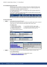
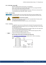
AKD2G-S Installation Manual, Safety 1 | 9   Setup

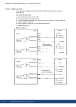
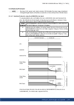
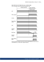
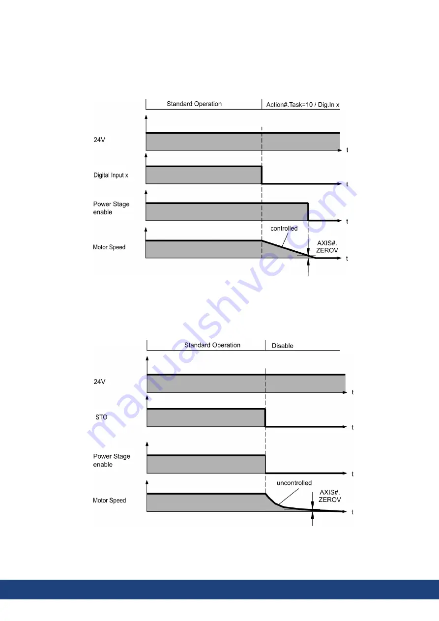
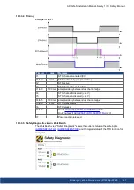
9.3.2.2 Switch-off behavior using a digital input (controlled stop)

This is a category 1 stop according to IEC 60204 (

# 19).

A digital input can be configured to bring the motor to a controlled stop and then disable the
drive and apply the holding brake.(if present). See the

WorkBench Online Help

for information

on configuring Digital Inputs.

If the drive detects the motor to be at zero velocity (AXIS#.ZEROV) or timeout occurs
(AXIS#.ZEROT), the motor brake is applied (

# 84).

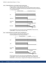
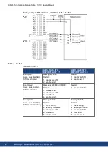
9.3.2.3 Switch-off behavior using STO input (uncontrolled stop)

This is a category 0 stop according to IEC 60204 (

# 19).

The STO input disables the power stage immediately.

If the drive detects the motor to be at zero velocity (AXIS#.ZEROV) or timeout occurs
(AXIS#.ZEROT), the motor brake is applied (

# 84). Set parameter AXIS#.MOTOR.

BRAKEIMM to 1 with vertical axes, to apply the motor holding brake immediately after STO.

126

Kollmorgen | kdn.kollmorgen.com | July 2020

Summary of Contents for AKD2G-S Series

Page 1: ...n Manual English Manual Edition C July 2020 Safety Edition S102 April 2020 Valid for AKD 2G S Hardware Revision A Part Number 907 200003 00 Original Document For safe and proper use follow these instructions Keep for future use Beta Drives All approvals are pending ...
Page 2: ...f Dr Johannes Heidenhain GmbH EtherCAT is a registered trademark and patented technology licensed by Beckhoff Automation GmbH Germany EtherNet IP is a registered trademark of ODVA Inc HIPERFACE is a registered trademark of Max Stegmann GmbH PROFINET is a registered trademark of PROFIBUS and PROFINET International PI Windows is a registered trademark of Microsoft Corporation Current patents US Pate...

Page 3: ...4 5 Decommissioning 23 4 6 Maintenance and cleaning 23 4 7 Disassembly 23 4 8 System Repair 24 4 9 Disposal 24 5 Package 25 5 1 Package Supplied 26 5 2 Nameplate 26 5 3 Part Number Scheme 27 6 Technical description and data 28 6 1 The AKD2G Family of Digital Drives 29 6 2 Ambient Conditions Ventilation and Mounting Position 31 6 3 Mechanical Data 31 6 4 Performance Data 32 6 5 Electrical data 33 6...

Page 4: ...on 52 8 4 1 Recommendations for EMI noise reduction 52 8 4 2 Shielding with external shielding busbar 53 8 4 2 1 Shielding Concept 53 8 4 2 2 Shielding Busbar 54 8 4 3 Shielding connection to the drive 55 8 4 3 1 Shielding Concept 55 8 4 3 2 Grounding plates and shield connection clamps 56 8 4 3 3 Motor connector X1 X2 with shielding connection 56 8 5 Connection Overview 57 8 5 1 Connector Positio...

Page 5: ...X22 89 8 9 5 4 Feedback Connector X23 90 8 9 5 5 Feedback Connector X41 SFA accessory 91 8 10 EEO Electronic Gearing Master Slave 92 8 10 1 Emulated Encoder Output EEO 92 8 10 2 Electronic Gearing 94 8 10 3 Master Slave control 94 8 10 3 1 Master Slave using X22 94 8 10 3 2 Master Slave using optional X23 or X41 94 8 11 EtherNet Fieldbus Interface X11 X12 95 8 11 1 EtherCAT 95 8 11 2 PROFINET avai...

Page 6: ...122 9 3 Switch On and Switch Off Behavior 123 9 3 1 Switch on behavior in standard operation 124 9 3 2 Switch off behavior 125 9 3 2 1 Switch off behavior using the AXIS DIS command 125 9 3 2 2 Switch off behavior using a digital input controlled stop 126 9 3 2 3 Switch off behavior using STO input uncontrolled stop 126 9 3 2 4 Switch off behavior in the event of a fault 127 9 4 Fault and Warning ...

Page 7: ...1 4 7 Ge n e r a l I n f o r ma t i o n 1 4 7 10 6 1 3 AXIS SAFE STO ACTIVE 148 De s c r i p t i o n 1 4 8 Co n t e x t 1 4 8 Ve r s i o n s 1 4 8 Ge n e r a l I n f o r ma t i o n 1 4 8 10 6 1 4 AXIS SAFE STO REPORTFAULT 148 De s c r i p t i o n 1 4 8 Co n t e x t 1 4 8 Ve r s i o n s 1 4 8 Ge n e r a l I n f o r ma t i o n 1 4 8 11 Approvals 149 11 1 Conformance with UL cUL 150 11 2 Conformance ...

Page 8: ... AKD2G S Installation Manual Safety 1 8 Kollmorgen kdn kollmorgen com July 2020 ...
Page 9: ...neral 2 1 About this Installation Manual 10 2 2 Using the PDF Format 10 2 3 Symbols Used 11 2 4 Abbreviations Used 12 AKD2G S Installation Manual Safety 1 2 General Kollmorgen kdn kollmorgen com July 2020 9 ...

Page 10: ...line Help describes how to use your drive in common applications It also provides tips for maximizing your system performance with the AKD2G The Online Help includes the Parameter and Command Reference Guide which provides information for the parameters and commands used to program the AKD2G CAN BUS Communication describes how to use your drive in CANopen applications EtherCAT Communication descri...

Page 11: ... symbol indicates important notes Warning of a danger general The type of danger is specified by the text next to the symbol Warning of danger from electricity and its effects Warning of danger from hot surface Warning of danger from suspended loads Warning of danger from automatic start Drawing symbols Symbol Description Symbol Description Signal ground Diode Chassis ground Relay Protective earth...

Page 12: ...tput EMC Electromagnetic compatibility EMF Electromagnetic force FS1 FS2 FS3 Functional Safety Option 1 2 3 FSoE Fail safe over EtherCAT KAS Kollmorgen Automation Suite KAS IDE Setup software Kollmorgen Automation Suite Integrated Development Environment KDN Kollmorgen Developer Network LED Light emitting diode LSB Low significant byte or bit MSB Most significant byte or bit NI Zero pulse OSSD Out...

Page 13: ... this 14 3 2 Use as Directed 16 3 3 Prohibited Use 17 3 4 Warning note labels 17 3 5 Shock hazard Protection 18 3 6 Stop Emergency Stop Emergency Off 19 AKD2G S Installation Manual Safety 1 3 Product Safety Kollmorgen kdn kollmorgen com July 2020 13 ...

Page 14: ...f the product see product label This number is the link between your product and the manual The product Hardware Revision Number must match the Hardware Revision Number on the cover page of the manual Pay attention to the technical data Adhere to the technical data and the specifications on connection conditions If permissible voltage values or current values are exceeded the devices can be damage...

Page 15: ...inet doors closed Built in protection measures such as insulation or shielding may not be removed Work on the electrical installation may only be performed by trained and qualified personnel in compliance with the regulations for safety at work and only with switched off mains supply and secured against restart Never undo any electrical connections to the drive while it is live There is a danger o...

Page 16: ...ries can be supplied as follows AKD2G Sxx 6Vxx 1 2 or 3 phase industrial supply networks not more than 10 kA symmetrical rated current at 120 V and 240 V or DC supply AKD2G Sxx 7Vxx 3 phase industrial supply networks not more than 10 kA symmetrical rated current at 240 V 400 V and 480 V or DC supply Connection to other voltage types of supply networks is possible with an additional isolating trans...

Page 17: ...ons oils vapors dusts ships or offshore applications The drive must not be connected directly to the Internet If the network to which the drive is connected is not secured according to state of the art information technology this could be a functional safety risk 3 4 Warning note labels 3 4 1 Notes placed on the product Wait 5 minutes after removing power before servicing 3 4 2 Adhesive label in t...

Page 18: ...chinery residual current protective devices RCDs can be used provided the requisite regulations are complied with The AKD2G is a 3 phase system with a B6 bridge Therefore RCDs which are sensitive to all currents must be used in order to detect any DC fault current Rated residual currents in the RCDs 10 to 30 mA Protection against indirect contact personal fire protection for stationary and mobile ...

Page 19: ...must have priority over assigned start functions The following stop categories are defined Stop Category 0 Shut down by immediate switching off the energy supply to the drive machinery this is an uncontrolled shut down For stop without using safety functions like STO set AXIS DISMODE to 0 The safety function STO stops the drive as required by Stop Category 0 IEC 62061 Stop Category 1 A controlled ...

Page 20: ...ery that could cause dangerous situations must be switched off as fast as possible without causing any further hazards Stop Category 0 or must be controlled in such a way that any movement that causes danger is stopped as fast as possible Stop Category 1 The reset must not initiate a restart 3 6 3 Emergency Off The Emergency Off function is used to switch off the electrical power supply of the mac...

Page 21: ...age 22 4 4 Installation setup and normal operation 23 4 5 Decommissioning 23 4 6 Maintenance and cleaning 23 4 7 Disassembly 23 4 8 System Repair 24 4 9 Disposal 24 AKD2G S Installation Manual Safety 1 4 Product life cycle handling Kollmorgen kdn kollmorgen com July 2020 21 ...

Page 22: ...ble damage Inform the shipper and the manufacturer of any damage to the package or product 4 2 Packaging The AKD2G packaging consists of recyclable cardboard with inserts and a label on the out side of the box Model Package mm HxWxL Total Weight kg AKD2G Sxx 6V03 to 6V12 158 x 394 x 292 4 2 AKD2G Sxx 7V03 to 7V12 158 x 394 x 292 4 3 Mating connectors are not included in the package of a standard d...

Page 23: ...e Avoid that liquid enters the device The inside of the unit can only be cleaned by the manufacturer Opening the device voids the warranty To clean the device exterior 1 Decommission the device see chapter 4 5 Decommissioning 2 Casing Clean with Isopropanol or similar cleaning solution Caution Highly Flammable Risk of injury by explosion and fire Observe the safety notes given on the cleaning liqu...

Page 24: ...ange of other drive system parts If parts of the drive system for example cables must be replaced proceed as follows 1 Decommission the device see chapter 4 5 Decommissioning 2 Exchange the parts 3 Check all connections for correct fastening 4 Setup the system as described in the Installation Manual 4 9 Disposal To dispose the unit properly contact a certified electronic scrap disposal merchant In...

Page 25: ...5 Package 5 1 Package Supplied 26 5 2 Nameplate 26 5 3 Part Number Scheme 27 AKD2G S Installation Manual Safety 1 5 Package Kollmorgen kdn kollmorgen com July 2020 25 ...

Page 26: ...es Motor mating connector X1 X2 SubD X23 X41 for Feedback RJ25 X13 X14 for CAN Bus and RJ45 X11 X12 X20 for Service and EtherNet Fieldbus Accessories sold separately Accessories must be ordered separately if required see regional Accessories Manual EMC filters for mains supply voltage categories C2 or C3 External regen resistor Mating connector kits Motor mating connector Hybrid cable Assembled hy...

Page 27: ...ways Example AKD2G SPE 7V06S A1IO 0000 AKD2G IP20 housing position indexer EtherCAT 240 V to 480 V mains supply 6 A rated current single axis Plattform Revision A dual channel STO SIL2 PLd with additional I O connector X22 uncoated no mating connectors Example AKD2G SPE 6V03D A1F3 A000 A AKD2G IP20 housing position indexer EtherCAT 120 V to 240 V mains supply 2 x 3 A rated current dual axis Plattf...

Page 28: ...1 The AKD2G Family of Digital Drives 29 6 2 Ambient Conditions Ventilation and Mounting Position 31 6 3 Mechanical Data 31 6 4 Performance Data 32 6 5 Electrical data 33 6 6 Electrical Motor Braking 37 6 7 LCD Display and Push buttons B1 B2 39 6 8 SD Card Slot 41 28 Kollmorgen kdn kollmorgen com July 2020 ...

Page 29: ...ase AC supply 5 to 110 of rated AC voltage over 47 to 63 Hz Con nection to higher AC voltage mains only by using isolating transformer DC supply voltage range 5 to 110 of rated DC voltage Fusing to be provided by the user Three phase bridge rectifier integral soft start circuit DC bus link voltage can be connected in parallel for power sharing Floating current sensors measure actual motor current ...

Page 30: ...el STO per axis 133 Connector Options IO X22 connector with additional digital inputs and outputs F3 X23 connector for conventional motor feedbacks Resolver SFD Tamagawa Smart Abs Comcoder 1Vp p Sin Cos encoders incremental encoders EnDAT 2 1 2 2 and HIPERFACE DX all possible connectors for extended I O and feedback connections Customization 0000 uncoated PCBs standard 0xxx uncoated PCBs customize...

Page 31: ...ass L according to IEC 61800 2 Drive protection IP 20 according to IEC 60529 Drive EMC immunity Increased immunity according to EN 61800 5 2 Mounting Vertical position in a cabinet with protection of at least IP 54 Minimum cabinet size WxHxD 406 x 406 x 254 mm Ventilation Built in fan in all drive variants The drive shuts down in case of excessively high temperature in the control cabinet Make sur...

Page 32: ...requency dynamic kHz 5 2 4 1 3 5 3 5 Voltage rise speed dU dt kV µs 7 0 7 0 7 0 7 0 Current Loop Update Period µs 1 28 1 28 1 28 1 28 Velocity Loop Update Period µs 62 5 62 5 62 5 62 5 Position Loop Update Period µs 250 250 250 250 Current Loop Bandwidth Hz 3000 3000 3000 3000 Velocity Loop Bandwidth Hz 750 750 750 750 Position Loop Bandwidth Hz 350 350 350 350 Max motor electrical frequency Hz 59...

Page 33: ...240 V at 480 V kVA 1 3 2 2 4 0 2 7 4 4 7 2 Rated input current A 3 2 5 3 9 7 3 2 5 3 8 7 Max inrush current A 10 Rated DC bus link voltage VDC 310 620 6 5 1 3 Mains supply data DC type AKD2G Sxx S Input data Units 6V03S 6V06S 6V12S 7V03S 7V06S 7V12S Operational supply voltage DC DC VDC 17 to 370 34 to 740 Rated supply voltage VDC 340 680 Permitted switch on off frequency 1 h 30 Rated input power a...

Page 34: ... 240 VAC kW 2 1 4 2 6 3 at 3 x 120 VAC kW 1 5 3 4 5 at 3 x 240 VAC kW 3 0 6 0 9 0 3 0 6 0 10 at 3 x 400 VAC kW 5 0 10 16 5 at 3 x 480 VAC kW 6 0 12 20 at 170 VDC kW 1 5 3 4 5 at 340 VDC kW 3 0 6 0 9 0 3 0 6 0 10 at 565 VDC kW 5 0 10 16 5 at 680 VDC kW 6 0 12 20 Noise emission at 1 m low high speed fan dB A 50 60 Thermal dissipation disabled W 12 12 12 12 12 12 Thermal dissipation at rated current ...

Page 35: ... kVA 2 2 4 0 4 4 7 2 Rated input current A 5 3 9 7 5 3 8 7 Max inrush current at 240 V 480 V 20 C A 10 Rated DC bus link voltage VDC 310 620 6 5 2 3 Mains supply data DC type AKD2G Sxx D Input data Units 6V03D 6V06D 7V03D 7V06D Operational supply voltage DC DC VDC 17 to 370 34 to 740 Rated supply voltage VDC 340 680 Permitted switch on off frequency 1 h 30 Rated input power at 340 V at 680 V kW 1 ...

Page 36: ...0 VAC kW 1 1 1 1 2 1 2 1 at 1 x 240 VAC kW 2 1 2 1 4 2 4 2 at 3 x 120 VAC kW 1 5 1 5 3 0 3 0 at 3 x 240 VAC kW 3 0 3 0 6 0 6 0 3 0 3 0 6 0 6 0 at 3 x 400 VAC kW 5 0 5 0 10 10 at 3 x 480 VAC kW 6 0 6 0 12 12 at 170 VDC kW 1 5 1 5 3 0 3 0 at 340 VDC kW 3 0 3 0 6 0 6 0 3 0 3 0 6 0 6 0 at 565 VDC kW 5 0 5 0 10 10 at 680 VDC kW 6 0 6 0 12 12 Noise emission at 1 m low high speed fan dB A 50 60 Thermal d...

Page 37: ...tor depending on the applic ation requirements External regen resistors are described in the regional Accessories Manual 6 6 2 1 Functional description 1 Individual drives not coupled through the DC bus link circuit DC DC When the energy fed back from the motor has an average or peak power that exceeds the pre set level for the brake power rating the drive generates the warning W2010 Regen Energy ...

Page 38: ...y in capacitors 20 Ws 9 35 DC Bus Capacitance µF 2460 depends on connected regen resistor power 6 6 2 3 Technical data for AKD2G Sxx 7V Technical data for the regenerative circuit depends on the drive type and the mains voltage Supply voltages capacitance and switch on voltages are all nominal values Brake circuit AC Supply AKD2G Sxx Rated data Units 240V 400V 480V 7V03S 7V06S 7V12S 7V03D 7V06D Re...

Page 39: ...upply to boot from an on board recovery image The fallback image includes a set of bootloader operational and control FPGA that implements sufficient pro gramming support to update missing or corrupt files LCD display Left Colored section Color axis status enabled disabled or faulted First icon axis command source analog service electronic gearing or fieldbus Second icon axis operation mode torque...

Page 40: ...xis 1 information the bottom section those for axis 2 Single axis LCD display For single axis drives the top section shows axis 1 information while the section between the center and bottom bars is a data area where some important actual values of the axis are vis ible position velocity current 40 Kollmorgen kdn kollmorgen com July 2020 ...

Page 41: ...eatures can be started from the drive display using push buttons B1 B2 Supported SD card types SD cards are formatted by the manufacturer The following table outlines the SD card types and AKD2G support SD Type File System Capacity Supported SD SDSC FAT16 1MB to 2GB YES SDHC FAT32 4GB to 32GB YES SDXC exFAT Microsoft 32GB to 2TB NO Features Boot AKD2G with data from SD card Remove 24V Apply 24V wi...

Page 42: ... S Installation Manual Safety 1 7 Mechanical Installation 7 Mechanical Installation 7 1 Important Notes 43 7 2 Guide to Mechanical Installation 43 7 3 Dimensions 44 42 Kollmorgen kdn kollmorgen com July 2020 ...

Page 43: ...ools are required at a minimum to install the AKD2G your specific install ation may require additional tools M5 hexagon socket cap screws ISO 4762 4 mm hexagon ball head screwdriver No 2 Phillips head screwdriver Small slotted screwdriver Install the drive unit as follows 1 Prepare the site Mount the drive in a closed control cabinet ambient conditions 31 The site must be free from conductive or c...

Page 44: ...ne width and height dimensions are measured on footprint level mounting plate Dimensions on the front plate are slightly smaller All dimensions in mm Dimensions in mm A A1 B B1 C D E F G H M P AKD2G Sxx 6V 3 to 12 A 221 232 235 303 76 221 5 36 5 8 11 5 7 78 40 AKD2G Sxx 7V 3 to 12 A 221 232 272 340 75 259 36 5 8 11 5 6 78 40 44 Kollmorgen kdn kollmorgen com July 2020 ...

Page 45: ...C Bus link X3 76 8 8 Regen resistor X3 78 8 9 Motor Power Brake and Feedback connection 79 8 10 EEO Electronic Gearing Master Slave 92 8 11 EtherNet Fieldbus Interface X11 X12 95 8 12 CAN Bus Interface X13 X14 98 8 13 Service Interface X20 101 8 14 Modbus TCP X20 102 8 15 I O Connection X21 X22 X23 103 AKD2G S Installation Manual Safety 1 8 Electrical Installation Kollmorgen kdn kollmorgen com Jul...

Page 46: ... voltage unsuitable motor or wrong wiring will damage the drive Check the combination of drive and motor Compare the rated voltage and current of the units Imple ment the wiring according to the matching connection diagram see 59 and following Make sure that the maximum permissible rated voltage at the terminals L1 L2 L3 or DC DC is not exceeded by more than 10 even in the most unfavorable circums...

Page 47: ...al regen resistor with fusing AKD2G Sxx 6V connect EMC filters shielded lines between filter and drive for second environment requirements to product category C2 Connect the auxiliary voltage supply Connect the main electrical supply Check maximum permitted voltage value 33 Check proper use of residual current circuit breakers RCD 18 Connect the PC 101 for setting up the drive 5 Check the wiring a...

Page 48: ...u must take care to provide an electrically conductive connection with the largest feasible sur face area between the unit indicated and the mounting plate in the control cabinet This con nection is for the effective grounding of HF interference and must not be confused with the PE symbol PE protective earth safety measure as per IEC 60204 8 3 2 Mating connectors Connectors X1 X2 X10T X21 X22 are ...

Page 49: ...the used cable material and the feedback type Cable functionality is only guaranteed up to the maximum length when using unmod ified Kollmorgen engineered cables Motor cables X1 X2 X4 X5 X23 X41 Length of motor power cables feedback cables and motor brake cables is equal AKM2G AKM Performance Line Cables Performance Line Cables Value Line Cables Feedback Max Length m Feedback Max Length m Feedback...

Page 50: ...ms 10 1A 1000 V Rated 80 C Current carrying capacity acc to IEC 60204 1 2006 Table 6 Column B2 The brackets show the shielding 4x1 5 4x1 5 2x0 75 10 1A I0rms 13 1A 4x2 5 4x2 5 2x1 0 13 1A I0rms 17 4A 4x4 4x4 0 2x1 0 17 4A I0rms 23A 4x6 4x6 0 2x1 0 23A I0rms 30A Motor Feedback Cable Type Cross Section mm Remarks Resolver 4x2x0 25 300 V rated 80 C Shielded twisted pairs The brackets show the shieldi...

Page 51: ...PE connection must therefore either be double implemented or a connection cable with 10mm cross section used In order to keep the impedance as low as possible we recommend a copper earthing strap for the PE connection on the PE block Wire the PE connections immediately after installing the devices as the first electrical con nection Now you insert all the other lines and connectors For disassembly...

Page 52: ...connector housings or shield connection clamps wherever pos sible For cables entering a cabinet connect shields on all 360 of the cable Never connect a simple pigtail For more information on shielding concepts 53 With separate mains filter maintain separation of leads entering and exiting the mains filter line power filter Locate the filter as close as possible to the point where the incoming powe...

Page 53: ... Kollmorgen recommends a star point shield con nection for example with a shielding busbar 8 4 2 1 Shielding Concept Example with AKD2G Sxx 6Vxx EMC filter and external regen resistor AKD2G S Installation Manual Safety 1 8 Electrical Installation Kollmorgen kdn kollmorgen com July 2020 53 ...

Page 54: ...es Risk of injury due to the spring force of the coil spring Use pincers 2 Squeeze together the coil spring and the supporting plate and push the busbar through the opening in the holder 3 Mount the busbar with the shield clamps fitted on the assembly plate Use either metal spacer bushes or screws with nuts and accessories to maintain a spacing of 50 mm Earth the bus bar using a single conductor w...

Page 55: ... drive by using grounding plates shield con nection clamps and a motor connector with strain relief and grounding plate 8 4 3 1 Shielding Concept Example with AKD2G Sxx 7Vxx dual axis AKD2G S Installation Manual Safety 1 8 Electrical Installation Kollmorgen kdn kollmorgen com July 2020 55 ...

Page 56: ...plate and strain relief Kollmorgen motor power and hybrid motor cables are configured with shield plate Strip the external cable sheath to a length of approx 80 mm taking care not to damage the braided shield Push the braided shield 1 back over the cable and secure with a rubber sleeve 2 or shrink sleeve Shorten all the wires apart from the protective earth PE wire green yellow by about 20 mm so t...

Page 57: ... AKD2G Sxx 6V The graphics shows an AKD2G with supply voltage 110 V to 240 V X2 is available with dual axis drives only Optional I O F3 or DX 27 AKD2G S Installation Manual Safety 1 8 Electrical Installation Kollmorgen kdn kollmorgen com July 2020 57 ...

Page 58: ... 8 Electrical Installation 8 5 2 Connector Position AKD2G Sxx 7V The graphics shows an AKD2G with supply voltage 240 V to 480 V X2 is available with dual axis drives only Optional I O F3 or DX 27 58 Kollmorgen kdn kollmorgen com July 2020 ...

Page 59: ...8 5 3 Wiring overview single axis drive AKD2G S Installation Manual Safety 1 8 Electrical Installation Kollmorgen kdn kollmorgen com July 2020 59 ...

Page 60: ...AKD2G S Installation Manual Safety 1 8 Electrical Installation 8 5 4 Wiring overview dual axis drive 60 Kollmorgen kdn kollmorgen com July 2020 ...

Page 61: ...M SFD3 or HIPERFACE DSL 8 5 5 2 X3 Mains regen resistor DC Bus 8 pin pitch 7 62 mm Screw terminals tightening torque 0 5 to 0 6 Nm 4 4 to 5 3 inlbs Locking screw tightening torque 0 5 Nm 4 4 inlbs Optional T version Mains supply External regen resistor DC Bus X3 5 to X3 6 must be shorted to use the built in regen resistor Remove the jumper to connect an external regen resistor Wiring example Power...

Page 62: ...onal RJ 25 X14 IN port X13 OUT port Up to 1 Mbit operation Node ID to be set by WorkBench Interface Details 98 Pin Signal Description Pin Signal Description 1 n c not used 4 CAN_low CAN bus low signal 2 Shield Chassis 5 CAN_GND CAN bus ground 3 CAN_high CAN bus high signal 6 n c not used 8 5 5 6 X20 Service RJ45 with built in green and yellow LEDs 100 10 Mbit EtherNet TCP IP Modbus TCP Supports au...

Page 63: ...N 61131 2 type 1 A10 Digital In DIN 8 Slow isolated sink type EN 61131 2 type 1 A11 STO A A1 Slow isolated sink fail safe STO axis 1 channel A B1 Analog Out AOUT 1 Analog Output 0 to 10 V B2 AGND Ground for analog I O B3 24 V 24 VDC for digital I O and STO B4 DGND Ground for digital I O and STO B5 Digital Out DOUT 9 Relay contact normally open 24 VDC 1A B6 Digital Out DOUT 9 Relay contact normally...

Page 64: ...ink type EN 61131 2 type 1 A17 AGND Ground for analog I O A18 Analog In AIN 2 Analog Input 10 V A19 Analog In AIN 2 A20 Digital In Out DIO 1 RS485 input or output A21 Digital In Out DIO 1 RS485 input or output B12 STO B A2 Slow isolated sink fail safe STO axis 2 channel B B13 Digital Out DOUT 5 Isolated high side 100 mA B14 Digital Out DOUT 6 Isolated high side 100 mA B15 Digital Out DOUT 7 Fast i...

Page 65: ...M R1 Ref DAT DAT DAT DAT DAT Zero Zero Zero Zero 7 COM R2 Ref DAT DAT DAT DAT DAT Zero Zero Zero Zero 8 Th Th Th Th Th Th Th Th Th Th Th 9 Th Th Th Th Th Th Th Th Th Th Th 10 5 V 5 V 5 V 5 V 5 V 5 V 5 V 5 V 5 V 5 V 5 V 5 V 5 V 11 0 V 0 V 0 V 0 V 0 V 0 V 0 V 0 V 0 V 0 V 0 V 0 V 0 V 12 S1 SIN A A SIN A A A A Step CW 13 S3 SIN A A SIN A A A A Step CW 14 S2 COS B B COS B B B B Dir CCW 15 S4 COS B B CO...

Page 66: ... EnDAT 2 2 HIPER FACE Sine Cos Sine Cos Hall Incr Enc Incr Enc Hall Hall Step Dir CW CCW 1 Hall U Hall U Hall U 2 CLK CLK CLK Hall V Hall V Hall V 3 CLK CLK CLK Hall W Hall W Hall W 4 SEN SEN SEN SEN SEN SEN SEN SEN SEN 5 SEN SEN SEN SEN SEN SEN SEN SEN SEN 6 COM R1 Ref DAT DAT DAT DAT Zero Zero Zero Zero 7 COM R2 Ref DAT DAT DAT DAT Zero Zero Zero Zero 8 Th Th Th Th Th Th Th Th Th Th Th 9 Th Th T...

Page 67: ...e with IEC 61800 voltage spikes 50 µs between phases must not exceed 1000 V Voltage spikes 50 µs between a phase and the PE hous ing must not exceed 2000 V 8 pin pitch 7 62 mm optional T version Wiring example 1 phase AC supply 68 2 phase AC supply 68 3 phase AC supply 69 DC supply 70 AKD2G Sxx 6V requires external EMC filter for use in industrial environment product category C Mating connector da...

Page 68: ... the user Use filter type FN2090 refer to the Accessor ies Manual for more information Use shielded cable between filter and drive Two phases AC mains AKD2G Sxx 6V Directly to two phase supply network without neutral line Activate single phase supply VBUS THREEPHASE 0 Set VBUS ACNOMINAL to desired nominal AC line voltage for lines other than nominal rated VAC AC line filtering to be provided by th...

Page 69: ... cable between filter and drive AKD2G Sxx 6V Motor cable 10 m use filter FN 3288 in industrial environment category C2 Motor cable 10 m use filter FN 3288 in industrial environment category C3 AKD2G Sxx 7V Motor cable 10 m no filter in industrial environment category C3 Motor cable 10 m use filter FN 3288 in industrial environment category C2 Motor cable 10 m use filter FN 3288 in industrial envir...

Page 70: ...ing the drive from the AC line input connections the drive s energy absorption and energy dissipation mechanisms can work normally DC Supply to DC Bus lines X3 7 8 When wiring DC power supply to the drive DC Bus terminals X3 pins 7 and 8 the user is responsible for current and power management using additional external devices User resposibility The power supply system design must ensure inrush cu...

Page 71: ...gle drives line fusing F1 F2 F3 depends on sum of current and cabinet requirements Filters for special EMC requirements only 151 FN1 FN2 FN3 maximum rating 30 A FN1 FN2 FN3 recommended rating see table below Drive Model FN1 FN2 FN3 Ampere rating Example class J Eaton Example class J Ferraz Shawmut AKD2G Sxx 6V03S 10 A Time Delay LPJ10SP DFJ10 AJT10 HSJ10 AKD2G Sxx 6V06S AKD2G Sxx 6V03D 10 A Time D...

Page 72: ...rent FN1 FN2 FN3 Ampere rating Example class J Eaton Example class J Ferraz Shawmut 6 A to 30 A 30 A Time Delay LPJ30SP DFJ30 AJT30 HJ30 AC supply single drives automatic circuit breakers F1 F2 F3 depends on sum of current and cabinet requirements Filters for special EMC requirements only 151 FN maximum rating 30 A FN recommended rating and regional approvals see table below Drive Model Ampere rat...

Page 73: ...m current FN recommended rating and regional approvals see table below Group sum current Ampere rating SCCR rating Example UL Eaton or ABB Example CE Siemens AKD2G Sxx 6V 6 A to 9A 15 A 10 kA SU203M K15 3VA51954EC310A 12 A to 15 A 20 A 10 kA SU203M K20 3VA51204EC310A 18 A to 24 A 30 A 10 kA SU203M K30 3VA51304EC310A 27 A to 36 A 30 A 10 kA SU203M K30 3VA51304EC310A AKD2G S Installation Manual Safe...

Page 74: ...e table below Drive Model Ampere rating Example UL Eaton Example CE Mersen AKD2G Sxx 6V03S 10 A Time Delay DFJ 10 HP6M10 AKD2G Sxx 6V06S AKD2G Sxx 6V03D 15 A Time Delay DFJ 15 HP6M15 AKD2G Sxx 6V12S AKD2G Sxx 6V06D 15 A Time Delay DFJ 15 HP6M15 AKD2G Sxx 7V03S 10 A Time Delay FWP 10B HP10M10 AKD2G Sxx 7V06S AKD2G Sxx 7V03D 10 A Time Delay FWP 10B HP10M10 AKD2G Sxx 7V12S AKD2G Sxx 7V06D 15 A Time D...

Page 75: ... voltage drop control current without motor brake A 1 control current with one motor brake A 3 1 control current with two motor brakes A 5 2 8 6 2 1 Fusing Use 24 VDC supply manufacturers recommendation for fusing 8 6 2 2 Wiring example 24 VDC supply Maximum current for one string of daisy chained X10T connectors is 20 A The sum control current of connected drives should not extend 20 A With the d...

Page 76: ...gths In this case no fuse for line protection is required The drives can be destroyed if DC bus link voltages are different Only drives with mains supply that share the same AC branch over current protection devices identical mains sup ply voltage may have the DC bus links interconnected Interconnection of DC bus links works best in systems powered by 3 phase AC or DC power Consult Kollmorgen for ...

Page 77: ...current in order to limit any possible resulting dam age Fgroup fuses cannot avoid damage by current peaks completely 8 7 3 Wiring example with busbar If a device fails in this system due to a short circuit only its fuses Fbus are tripped and the rest of the network continues uninterrupted The solid busbars can conduct significantly lar ger currents than T connectors because the compensating curre...

Page 78: ...en resistor Refer to the WorkBench online help for parameter setting REGEN EXT REGEN REXT REGEN WATTEXT Pin Label Signal Description 5 Ri RBint internal Regen resistor 6 Re RB external Regen resistor 7 DC RBext external Regen resistor 8 8 1 Fusing and Wiring FB1 FB2 fusing Drive Model Ampere rating 240V Ampere rating 480V UL region example CE Region example Siba all AKD2G Sxx 10A 40A Eaton FWP xxA...

Page 79: ...tion feedback SFD3 or DSL Axis 2 dual cable connection 80 commutation feedback EnDAT HIPERFACE Resolver etc by using SFA Axis 1 dual cable connection 82 commutation feedback Resolver SFD EnDAT HIPERFACE BiSS SinCos ComCoder Hall SmartAbs etc by using X23 position feedback X21 Step Direction X22 Step Direction or incremental encoder Axis 2 single cable connection 80 commutation feedback SFD3 or DSL...

Page 80: ...X22 X23 Dual axis standard X1 X2 X21 X22 Dual axis with Option DX X1 X2 X21 X22 X23 8 9 2 1 Motor Power Brake and Feedback connectors X1 X2 X1 Feedback 1 X2 Feedback 2 Motor Power 4 pin pitch 7 62 mm Motor Brake 2 pin pitch 3 81 mm Motor Feedback 2 pin pitch 3 81 mm Cable length 49 Use Kollmorgen cables Mating connector data 48 Feedback types SFD3 HIPERFACE DSL Rated voltage 11 V Rated current is ...

Page 81: ...connector data 48 Cable length 49 Connector Functionality Pinout Wiring X21 Step Direction CW CCW 88 X22 Step Direction CW CCW Incr Encoder EnDAT BiSS 89 X23 Several conventional feedback types 90 AKD2G S Installation Manual Safety 1 8 Electrical Installation Kollmorgen kdn kollmorgen com July 2020 81 ...

Page 82: ...ing master slave con nection are possible by using X21 X22 X23 depending on the drive version and physical restrictions X1 Feedback 1 X2 Feedback 2 Motor Power 4 pin pitch 7 62 mm Motor Brake 2 pin pitch 3 81 mm SFA connection 2 pin pitch 3 81 mm Feedback types see SFA connectivity 91 X23 Feedback 3 SubD HD 15 poles Feedback types see X23 connectivity 90 X21 Feedback 4 2 x 11 pins left connector A...

Page 83: ...Direction CW CCW Incr Encoder EnDAT BiSS 89 X23 Several conventional feedback types 90 Feedback connector X1 X2 X41 Conventional feedback systems can be connected to X1 or X2 by using the optional feed back adapter SFA SFA offers the additional connector X41 Connector X1 is a standard connector Input for SFD3 DSL or SFA Connector X2 is standard for dual axis drives Input for SFD3 DSL or SFA SFA ad...

Page 84: ... axis 2 or secondary brake for axis 1 No functional Safety Serious injury could result when the load is not properly blocked The internal brake function does not ensure functional safety Functional safety e g with hanging load vertical axes requires an additional brake controlled e g from the other axis or externally from a safety controller The brakes can be mapped to an axis with WorkBench The H...

Page 85: ...ult values The drive speed setpoint is internally driven down an adjustable ramp AXIS CS DEC to 0 V With default values the output for the brake is switched on when the speed has reached 5 rpm AXIS ZEROV for at least 6 ms AXIS ZEROT The rise tbrH and fall tbrL times of the holding brake that is built into the motor are different for the various types of motor AKD2G S Installation Manual Safety 1 8...

Page 86: ...annot commutate axis 1 Feedback channel Connector Usable for Pinout Feedback 1 X1 Axis 1 commutation feedback 87 X41 Axis 1 by using SFA on X1 commutation feedback 91 Feedback 2 X2 Axis 2 commutation feedback 87 Feedback 2 X41 Axis 2 by using SFA on X2 commutation feedback 91 Feedback 3 X23 commutation feedback velocity position command 90 Feedback 4 X21 commutation feedback velocity position comm...

Page 87: ... or HIPERFACE DSL Wiring example conventional Feedback types with SFA Electrical data Rated voltage 11 V Rated current is 350 mA simultaneously for X1 and X2 Pin Signal Description F COM SFD3 HIPERFACE DSL SFA F COM SFD3 HIPERFACE DSL SFA AKD2G S Installation Manual Safety 1 8 Electrical Installation Kollmorgen kdn kollmorgen com July 2020 87 ...

Page 88: ...onnector B pitch 3 5 mm Fast input isolated sink type EN 61131 2 type 1 Input for commutation or position feedback Input for Electronic Gearing 92 Mating connector data 48 Wiring example X21 Pin Step Direction CW CCW A3 Step CW A4 Direction CCW B3 24 VDC 24 VDC B4 Common DGND Common DGND 88 Kollmorgen kdn kollmorgen com July 2020 ...

Page 89: ...EEO2 92 Mating connector data 48 Wiring example Input EEO output connection is similar X22 Pin Step Direction CW CCW Increm Encoder BiSS B C EnDAT 2 2 A20 Step CW Track A CLK CLK A21 Step CW Track A CLK CLK B20 Direction CCW Track B DAT DAT B21 Direction CCW Track B DAT DAT A17 AGND AGND AGND AGND AGND Feedback power supply must be supplied and controlled by the user AKD2G S Installation Manual Sa...

Page 90: ...Resol ver BiSS B BiSS C EnDat 2 1 EnDat 2 2 HIPER FACE Sine Cos Sine Cos Hall Incr Enc Incr Enc Hall Hall Step Dir CW CCW 1 Hall U Hall U Hall U 2 CLK CLK CLK CLK Hall V Hall V Hall V 3 CLK CLK CLK CLK Hall W Hall W Hall W 4 SEN SEN SEN SEN SEN SEN SEN SEN SEN SEN 5 SEN SEN SEN SEN SEN SEN SEN SEN SEN SEN 6 COM R1 Ref DAT DAT DAT DAT DAT Zero Zero Zero Zero 7 COM R2 Ref DAT DAT DAT DAT DAT Zero Ze...

Page 91: ...ion EEO3 EEO4 92 Master Slave 94 Connect the flying leads of the SFA cable to X1 FB1 EEO3 or X2 FB2 EEO4 Operating Voltage 7 V to 12 V Maximum Load Current 350 mA X41 Pin SFD Resol ver BiSS B EnDat 2 1 EnDat 2 2 HIPER FACE Sine Cos Sine Cos Hall Incr Enc Incr Enc Hall Hall Step Dir CW CCW 1 Hall U Hall U Hall U 2 CLK CLK CLK Hall V Hall V Hall V 3 CLK CLK CLK Hall W Hall W Hall W 4 SEN SEN SEN SEN...

Page 92: ... WorkBench Online Help for more information When using a multispeed resolver more than 2 poles as commutation feedback the EEO will create only one zero pulse per each mechanical revolution of the motor The zero pulse is dependent on the motors starting position EEO1 4 are NOT compatible with 24V signal level Will be damaged if connected to 24V Technical characteristics X22 EEO2 Pulse outputs on t...

Page 93: ...A EEO3 EEO4 Pulse outputs on the SubD connector X41 are 3 signals A B and Index with 90 phase dif ference i e AquadB with a zero pulse If SFA is connected to X1 the logical output is EEO3 If SFA is connected to X2 or X5 the logical output is EEO4 5V TTL current 60 mA Max number of connected slaves is determined by the loading characteristics of the slaves 32 slaves can be driven if the input imped...

Page 94: ...everal AKD2G can be connected as slave drives to another AKD2G which acts as a mas ter The slave drives use the master s encoder output signal EEO 92 as command input and follow these commands velocity and direction 8 10 3 1 Master Slave using X22 The master is configured for EEO2 92 on X22 the Slave uses X22 for command input 8 10 3 2 Master Slave using optional X23 or X41 The master is configure...

Page 95: ...built in connector LEDs Conn Name Function X11 Out ERR Returns potentials communication failures Off No Error Blinking Invalid configuration Single Flash Local error Double Flash Process data watchdog X11 Out Link Activity On Blinking Physical link Data Traffic on Static off No link X12 In RUN Returns the device state Off INIT Blinking PRE OPERATIONAL Single Flash SAFE OPERATIONAL On OPERATIONAL F...

Page 96: ...exchange X11 Port 2 Link Activity ON Connection to the EtherNet OFF No connection to the EtherNet Flashing Sends receives EtherNet frames X12 Port 1 SF ON Watchdog timeout channel generic extended diagnosis present system error OFF No Error Flashing 2Hz DCP signal service is initiated via the bus X12 Port 1 Link Activity ON Connection to the EtherNet OFF No connection to the EtherNet Flashing Send...

Page 97: ...king Physical link Data Traffic on Static off No link X12 Port 1 MS Green On Device Operational Green Flashing Standby Red On Major Fault Red Flashing Minor Fault Red Green Flashing Self test Off No power X12 Port 1 Link Activity On Blinking Physical link Data Traffic on Static off No link Bus topology example EtherNet IP We suggest to use Kollmorgen ENCP cables For more possible system solutions ...

Page 98: ...8 a bus cable with a characteristic impedance of 120 Ω should be used The maximum usable cable length for reliable communication decreases with increasing transmission speed As a guide you can use the following values measured by Kollmorgen however these val ues are not assured limits Characteristic impedance 100 120 Ω Cable capacitance max 60 nF 1000 m Lead loop resistance 159 8 Ω 1000 m Transmis...

Page 99: ...8 12 2 CAN Bus Wiring AKD2G S Installation Manual Safety 1 8 Electrical Installation Kollmorgen kdn kollmorgen com July 2020 99 ...

Page 100: ...you must turn off the 24 V auxiliary supply for the drive and then turn it on again 8 12 5 CAN Bus Termination The last bus device on both ends of the CAN Bus system must have termination resistors The AKD2G has built in 132 Ω resistors that can be activated by connecting pins 1 and 6 An optional termination plug is available for AKD2G AKD CAN TERMINATION The optional termination plug is an RJ25 c...

Page 101: ...ating position control and motion block parameters can be set up by using the setup software on an ordinary commercial PC 121 Connect the service interface X20 of the drive to an EtherNet interface on the PC directly or by using a network switch while the supply to the equipment is switched off Use stand ard Cat 5 EtherNet cables for connection in some cases crossover cables will also work Confirm...

Page 102: ... the AKD2G the green LED on the RJ45 connector and on your HMI or switch are both illuminated If both LEDs are illuminated then you have a good elec trical connection The following are required to connect an HMI to the drive The HMI must support Modbus TCP It must have EtherNet hardware and a driver for Modbus TCP though the driver does not have to be made specifically for the AKD2G family The sub...

Page 103: ...DIN 8 B10 Digital Out DOUT 4 A11 STO A A1 B11 STO B A1 X22 optional for single axis drives standard for dual axis drives Pin Signal Pin Signal A12 STO A A2 dual axis B12 STO B A2 dual axis A13 Digital In DIN 9 B13 Digital Out DOUT 5 A14 Digital In DIN 10 B14 Digital Out DOUT 6 A15 Digital In DIN 11 B15 Digital Out DOUT 7 A16 Digital In DIN 12 B16 Digital Out DOUT 7 A17 AGND B17 Digital Out DOUT 8 ...

Page 104: ...F 5 VDC to 5 VDC max 15 mA galvanic isolation for 60 VDC delay activation de activation about 5 µs 500 µs Digital outputs Digital Out DOUT 1 to 6 max 30 VDC 100 mA short circuit proof galvanic isolation for 60 VDC delay activation de activation about 5 µs 300 µs Digital outputs Digital Out DOUT 7 to 8 volt free contacts max 30 VDC 100 mA sink or source galvanic isolation for 24 VDC from PE delay a...

Page 105: ...et drift typ 250 µV C Gain or slope tolerance 3 Nonlinearity 0 1 of full scale or 12 5 mV Common Mode Rejection Ratio 30 dB at 60 Hz Input impedance 13k Ωs Signal to noise ratio referred to full scale AIN CUTOFF 3000 Hz 14 bit AIN CUTOFF 800 Hz 16 bit Analog Input Wiring Diagram Application examples for set point input Analog In reduced sensitivity input for setting up jog operation pre control ov...

Page 106: ...he I O cable leaves the cabinet it must be EMC shielded Technical characteristics Output voltage range referring to AGND 0 to 10 V Resolution 16 Bit and fully monotonic Update rate 4 kHz Unadjusted offset 50 mV Offset drift typ 250 µV C Gain or slope tolerance 3 Nonlinearity 0 1 of full scale or 20 mV Output impedance 110 Ω Specification complies with IEC 61131 2 Table 11 3 dB Bandwidth 8 kHz Maxi...

Page 107: ...t must be EMC shielded Depending on the selected function the inputs are high or low active Digital input filter can be set in WorkBench to change sensitivity of the inputs see Online Help 8 15 5 1 Digital In 1 and 2 These inputs IEC 61131 2 Type 1 are particularly fast and are therefore suitable for position latch functions They can also be used as 24 V inputs for electronic gearing 92 Technical ...

Page 108: ...tal In 3 HW Enable Axis 1 Digital In 4 HW Enable Axis 2 Digital In 5 12 off Choose the function you require in WorkBench For more information refer to WorkBench Technical characteristics Floating reference common line is DGND High 11 to 30 V 2 to 15 mA Low 5 to 5 V 15 mA Update rate firmware reads hardware input state every 250 µs Wiring example 108 Kollmorgen kdn kollmorgen com July 2020 ...

Page 109: ...l Will be damaged if connected to 24V Technical characteristics if configured as input RS485 reference common line is AGND No wire break detection Digital IN OUT 1 2 Selectable DC termination for differential or single ended input Update rate firmware reads hardware input state every 250 µs Wiring example AKD2G S Installation Manual Safety 1 8 Electrical Installation Kollmorgen kdn kollmorgen com ...

Page 110: ... with 24V signal level Will be damaged if connected to 24V Technical characteristics if configured as input RS485 reference common line is 0V No wire break detection Digital IN OUT 3 4 Selectable DC termination for differential or single ended input Digital IN OUT 5 6 AC termination for single ended input Update rate firmware reads hardware input state every 250 µs Wiring example 110 Kollmorgen kd...

Page 111: ... I O lines is 3 m inside the cabinet If the I O cable leaves the cabinet it must be EMC shielded Choose the required action in the setup software Messages from pre programmed actions A list of actions is included in the WorkBench If an output is programmed it must be saved to the drive 8 15 6 1 Digital Out 1 to 6 These outputs are programmable with the setup software By default all outputs are off...

Page 112: ... not pro grammed off Technical characteristics The outputs can switch 5 V to 30 V Galvanic isolation for 24 VDC from PE The two channels are isolated from one another and not referred to a common potential Output current max 100 mA Can be wired as sinking or sourcing see examples below Update rate 250 µs Wiring examples 112 Kollmorgen kdn kollmorgen com July 2020 ...

Page 113: ...ion Update rate 250 µs 8 15 6 4 Digital In Out 3 to 6 X23 can be used for digital I O The channels can be defined as inputs or outputs For pro gramming refer to WorkBench Technical characteristics if configured as output RS485 reference common line is 0V No wire break detection Digital IN OUT 3 4 Selectable DC termination for differential or single ended output Digital IN OUT 5 6 AC termination fo...

Page 114: ... WorkBench By default the output function is defined as ready to operate output by action parameter If an inductive load relay or similar is used a freewheeling diode must be added to the load Technical characteristics Relay output max 30 VDC or 42 VAC 1 A Galvanic isolation for 24 VDC from PE Time to close max 10 ms Time to open max 10 ms 114 Kollmorgen kdn kollmorgen com July 2020 ...

Page 115: ...tes 116 9 2 Guide to drive setup 117 9 3 Switch On and Switch Off Behavior 123 9 4 Fault and Warning Messages 130 9 5 Troubleshooting 131 AKD2G S Installation Manual Safety 1 9 Setup Kollmorgen kdn kollmorgen com July 2020 115 ...

Page 116: ...he drive might restart automatically after power on voltage dip or interruption of the supply voltage depending on the parameter setting If parameter AXIS ENDEFAULT is set to 1 then place a warning sign WARNING Possible Automatic Restart or similar to the machine Ensure that power on is not possible while humans are in a dangerous zone of the machine High Temperature Risk of minor burns The heat s...

Page 117: ... wiring for drive testing as described below 4 Make sure you have on hand the following information about the drive components rated mains supply voltage motor type motor data if the motor type is not listed in the motor database feedback unit built into the motor type poles lines protocol moment of inertia of the load 9 2 1 2 Minimum wiring for drive test without load example This wiring diagram ...

Page 118: ...e unique MAC address is pre defined by the manufacturer see nameplate Service IP Address The AKD2G service port X20 supports auto IP DHCP and static IP addressing The drive is delivered with IP address 0 0 0 0 Depending on the connection switch or PC either DHCP or auto IP mechanism assignes a unique IP address WorkBench uses the IP address to detect AKD2G devices in the LAN and start com municati...

Page 119: ...xis and 3 Save parameter set to the drive Refer to the WorkBench Online Help for details 9 2 1 7 Enable the axis Hardware 1 Switch 24 V to the STO inputs X21 A11 B11 for axis 1 or X21 A12 B12 for axis 2 2 Switch 24 V to the digital inputs for Hardware Enable Axis 1 X21 A5 or 2 X21 A6 9 2 1 8 Move the motor axis 1 Select the axis in WorkBench 2 Enter Service Motion view 3 select Reversing check the...

Page 120: ... with the help of this software and during this procedure the drive can be controlled directly by the service functions Only professional personnel who have the relevant expertise 14 are permitted to carry out online parameter setting for a drive that is running Sets of data that have been stored on data media are not safe against unintended alteration by other persons Unexpected move could be the...

Page 121: ...tems are plug and play compatible Motor nameplate data is stored in the feedback device and read by the drive automatically at startup Non plug and play Kollmorgen motors are stored in WorkBench and can be loaded with one click using the Motor screen in the WorkBench software An extensive online help with integrated description of all variables and functions supports you in each situation 9 2 2 3 ...

Page 122: ...he setup software WorkBench Click it and follow the instructions Autostart function deactivated Insert the DVD into a free drive Click Start task bar then Run Enter the program call x index htm x correct DVD drive letter Click OK and proceed as described above Connection to the EtherNet interface of the PC Connect the interface cable to an EtherNet interface on your PC or to a Switch and to the AK...

Page 123: ...e Consult the WorkBench Online Help for configuring the parameter 0 The drive will report a F2007 undervoltage fault any time an under voltage condition occurs 1 default The drive will report a warning W2007 if not enabled The drive will report a fault if the drive is enabled when the condition occurs or an attempt is made to enable while an under voltage condition occurs Functional Safety The dri...

Page 124: ...tallation Manual Safety 1 9 Setup 9 3 1 Switch on behavior in standard operation The diagram below illustrates the correct functional sequence for switching the drive on 124 Kollmorgen kdn kollmorgen com July 2020 ...

Page 125: ...XIS DISMODE AXIS DISMODE controls the behavior of the AXIS DIS command issued through WorkBench or terminal or fieldbus 0 Disable axis immediately if the drive detects the motor to be at zero velocity AXIS ZEROV or timeout occurs brake is applied Category 0 stop according to IEC 60204 19 2 Use controlled stop to disable drive if the drive detects the motor to be at zero velocity AXIS ZEROV or time...

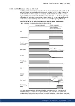
Page 126: ...nputs If the drive detects the motor to be at zero velocity AXIS ZEROV or timeout occurs AXIS ZEROT the motor brake is applied 84 9 3 2 3 Switch off behavior using STO input uncontrolled stop This is a category 0 stop according to IEC 60204 19 The STO input disables the power stage immediately If the drive detects the motor to be at zero velocity AXIS ZEROV or timeout occurs AXIS ZEROT the motor b...

Page 127: ...ch fault The next pages show examples for the possible fault behaviors The fault relay output DOUT9 switches the main contactor Emergency Off circuit Switch off behavior for faults that cause an immediate power stage disable This is a category 0 stop according to IEC 60204 19 If the drive detects the motor to be at zero velocity AXIS ZEROV or timeout occurs AXIS ZEROT the motor brake is applied 84...

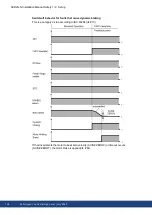
Page 128: ...vior for faults that cause dynamic braking This is a category 2 stop according to IEC 60204 19 If the drive detects the motor to be at zero velocity AXIS ZEROV or timeout occurs AXIS ZEROT the motor brake is applied 84 128 Kollmorgen kdn kollmorgen com July 2020 ...

Page 129: ...his is a category 2 stop according to IEC 60204 19 If the drive detects the motor to be at zero velocity AXIS ZEROV or timeout occurs AXIS ZEROT the motor brake is applied 84 AKD2G S Installation Manual Safety 1 9 Setup Kollmorgen kdn kollmorgen com July 2020 129 ...

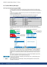
Page 130: ...ftware 90 Safety The display on the front panel of the drive shows the code of the fault or warning that occurred Navigate with B1 B2 to the Fault screen to see a short description of the fault or warning You can retrieve faults on a per axis basis with the parameter AXIS FAULTS where is the Axis number For retrieving warnings use AXIS WARNINGS or DRV WARNINGS Multiple faults may be present when a...

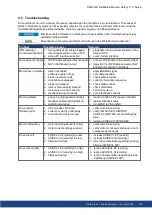
Page 131: ...k set up incorrectly 1 apply ENABLE signal 2 set software enable 3 check setpoint cable 4 correct motor phase sequence 5 check brake control 6 check mechanics 7 set motor pole no 8 set up feedback correctly Motor oscillates 1 gain is too high speed controller 2 feedback cable shielding broken 3 AGND not wired up 1 reduce AXIS VL KP speed controller 2 replace feedback cable 3 join AGND to CNC GND D...

Page 132: ... AKD2G S Installation Manual Safety 1 9 Setup 132 Kollmorgen kdn kollmorgen com July 2020 ...

Page 133: ...nctional Safety Option 1 S102 04 2020 Default setting STO active max length of unshielded digital I O lines 3 m trouble shooting updated description F9004 9005 updated SFF 75 STO certified 10 1 General notes 134 10 2 Verification 137 10 3 Safety Function Option 1 I O SIL2 PLd 137 10 4 Settings 143 10 5 Safety Faults Safety Warnings 144 10 6 Functional Safety Parameter Reference 146 AKD2G S Install...

Page 134: ...e accord ing to IEC 60417 6182 Parameterizing Functional Safety only by trained personnel with expertise appropriate to the complexity and safety integrity level of the drive system Verification Validation only by trained personnel after any changes to the installation The expertise of the personnel must be appropriate to the complexity and safety integrity level of the drive system Safe State The...

Page 135: ...ety functions must not be used if the drive is to be made inactive for Emergency Off situations In an Emergency Off situation the main relay is switched off by the Emergency Off button The STO function requires two channel control if the performance level SIL2 PLd Cat 3 in the system is to be achieved The connection of a constant 24 VDC voltage to one of the STO inputs is not permitted if the safe...

Page 136: ...ensation IEC 61800 2 class 3K3 Site altitude Up to 1000 m above mean sea level AMSL no restriction 1 000 to 2 000 m AMSL power derating 1 5 100 m Maximum altitude 2000 m AMSL Drive EMC immunity Increased immunity according to EN 61800 5 2 Drive Pollution level Pollution level 2 as per IEC 60664 1 Drive Vibration class Class 3M1 according to IEC 61800 2 Drive Shock class Class L according to IEC 61...

Page 137: ...splays fault F9000 1 Stop the axis to standstill 2 Caution Block vertical load 3 Disable the axis 4 Activate the STO function for example by opening the protective screen 5 The axis displays fault W9000 10 3 Safety Function Option 1 I O SIL2 PLd Beta drives Safety functions are neither approved nor certified yet Do not use this func tionality in applications with functional safety request until fu...

Page 138: ...s then bypassed and cannot be used I O hardware data Reference ground is DGND Galvanic isolation for 60 VDC Activation delay about 5 µs De activation delay about 500 µs Use 24 VDC 15 PELV power supply High level 17 VDC to 30 VDC 5 mA to 6 mA Low level 0 VDC to 5 VDC max 1 mA Pinout X21 Signal Description A11 STO A A1 STO channel A for axis 1 B11 STO B A1 STO channel B for axis 1 Drives with two ax...

Page 139: ...a vertical load when STO is active Add a safe mechanical blocking for instance a motor holding brake 10 3 3 2 Activation The digital STO inputs channel A and B must be connected to the output of a safety device which at least meets the requirements of PLd Cat 3 according to ISO 13849 Technical data of the safe inputs 138 If one of the STO inputs goes open circuit or 0 V then power supply to the mo...

Page 140: ... 1 deactivate STO 2 enable axis 1 Example 2 Axis 1 was enabled STO is activated Messages W9000 and F9000 Restart 1 disable axis 1 2 deactivate STO 3 clear fault 4 enable axis 1 Restart 1 deactivate STO Example 3 Axis 1 was disabled STO is activated faulty Message F9005 Restart 1 check wiring 2 remedy the cause 3 deactivate STO 4 clear fault 5 enable axis 1 Message F9005 Restart 1 check wiring 2 re...

Page 141: ... delay between dual channel edges t5 to t6 2 ms STO release delay t6 STO release t6 to t7 Zero if AXIS SAFE STO REPORTFAULT 0 Until no fault if AXIS SAFE STO REPORTFAULT 1 t7 Power section released 10 3 3 5 Safety Diagnostic view in WorkBench The WorkBench view Safety Diagnostic shows the current status on the safe inputs AXIS SAFE STO A AXIS SAFE STO B and the logical status of the STO function f...

Page 142: ...f AXIS SAFE STO REPORTFAULT If this parameter is set to 1 default value then the W9000 and F9000 will be triggered as described STO A A STO B A ENABLE Drive Message Motor Torque Safe State 0 V 0 V 0 V W9000 no yes 0 V 0 V 24 V F9000 no yes 24 V 24 V 0 V no no 24 V 24 V 24 V yes no 24 V 0 V 0 V F9005 no yes 24 V 0 V 24 V F9005 no yes 0 V 24 V 0 V F9005 no yes 0 V 24 V 24 V F9005 no yes different st...

Page 143: ...an 2 seconds on B2 returns the display to the previous screen B1 B2 Functions Description Boot from SD card Push both buttons during power up to boot with data from SD card Press the buttons first then hold it down while turning on the 24 V power supply Boot from flash fallback image Remove the SD card then press both buttons and hold them down while turning on the 24 V power supply to boot from a...

Page 144: ...igation The display on the front panel of the drive shows the code of the fault or warning that occurred Safety Faults and Warnings follow the same pattern and are identified by a four digit code 90 XX where 90 is the two digit group code and XX is a two digit ID Navigate with B1 B2 to the Fault screen to see a short description of the fault or warning See WorkBench Onlinehelp for details 144 Koll...

Page 145: ...or safety warning message is visible in the drive LCD dis play Refer to the Drive Safety Fault and Warning tables 145 A fault or warning message of another group than 90 is visible in the drive LCD display Refer to the drive fault and drive warnings tables 130 and more detailled descriptions in the WorkBench User Manual Safety faults and warnings are not visible reported AXIS SAFE STO REPORTFAULT ...

Page 146: ... related to Parameter CoE safety functions Acc Default Package Index Sub AXIS1 SAFE STO A RO n a n a 5007 3 AXIS2 SAFE STO A RO n a n a 5107 3 AXIS1 SAFE STO ACTIVE RO n a n a 5007 2 AXIS2 SAFE STO ACTIVE RO n a n a 5107 2 AXIS1 SAFE STO B RO n a n a 5007 4 AXIS2 SAFE STO B RO n a n a 5107 4 AXIS1 SAFE STO REPORTFAULT RW 1 Drive 5007 1 AXIS2 SAFE STO REPORTFAULT RW 1 Drive 5007 1 146 Kollmorgen kd...

Page 147: ... 1 Default Value N A Data Type Integer Stored in Non Volatile Memory No 10 6 1 2 AXIS SAFE STO B Description Indicates the state for STO B input Value Description 1 24V present STO inactive allowed to enable 0 24V not present STO active axis disabled Context For full STO information refer to STO Safe Torque Off 139 Versions Action Version Notes Implemented 02 00 00 000 General Information Type Rea...

Page 148: ...Non Volatile Memory No 10 6 1 4 AXIS SAFE STO REPORTFAULT Description This parameter indicates whether a Safe Torque Off STO fault will be created when the STO input is lost while the axis is enabled Value Description 1 STO fault is indicated when axis is enabled and an STO occurs default 0 STO fault is not indicated warning is still present Context For full STO information refer to STO Safe Torqu...

Page 149: ... cUL 150 11 2 Conformance with European Directives 151 11 3 Conformance with RoHS 152 11 4 Conformance with REACH 152 11 5 Functional Safety approval 152 11 6 Conformance with EAC 152 AKD2G S Installation Manual Safety 1 11 Approvals Kollmorgen kdn kollmorgen com July 2020 149 ...

Page 150: ... V 10 kA rms symmetrical Convient pour une installation de groupe moteur sur un circuit capable de délivrer pas plus de AKD2G Sxx 6V 240 V 10 kA symétriques rms AKD2G Sxx 7V 480 V 10 kA symétriques rms These drives provide solid state motor overload pro tection at 125 of the rated FLA current The drive overload trip point should not be set to less than 10 above the motor rated current AXIS IL FOLD...

Page 151: ... interference suppression such as additional external EMC fil ters Maximum distance for unshielded I O lines is 3 m inside the cabinet If the I O cable leaves the cabinet it must be EMC shielded AKD2G Sxx 6Vxx AKD2G Sxx 6Vxx drives do not have integrated ac line EMC filters External mains filters are described in the Accessories Manual 1 FN2090 3 FN3288 With external EMC mains filters for noise em...

Page 152: ...n offers 3 levels of functional safety implementation for AKD2G Functional Safety Option 1 STO SIL2 PLd 137 safe digital I O command Functional Safety Option 2 STO SS1 t SBC SBT SDB SIL3 PLe safe digital I O command or FSoE Functional Safety Option 3 STO SS1 t SS1 r SS2 SOS SLS SSM SSR SDI SLA SAR SLI SLP SCA SBC SDB SBT SIL3 PLe safe digital I O command or FSoE This manual is valid for AKD2G driv...

Page 153: ...emulation interface 92 EtherCAT 95 EtherNet Modbus TCP Protocol 102 EtherNet Fieldbus 95 EtherNet IP 97 F Factury Default Setting 138 Fault messages 130 Feedback Connection 86 Functional Safety FS 133 Functional Safety 1 FS1 137 Fusing 24V supply 75 Brake resistor 78 DC Bus Link 76 Mains supply 71 G Grounding 47 Grounding Plates 56 H Hardware requirements WorkBench 121 Hiperface DSL 80 I I O Conne...

Page 154: ...6 Electrical Installation 46 General 14 Mechanical Installation 43 Safety Properties 138 Safety Warnings 144 SD Card Slot 41 Service Interface 101 Setup 116 Setup Software 120 SFA 91 SFD3 80 Shield connection 53 Shielding 47 Shock hazard protection 18 Site 31 STO 139 Stop Function 19 Switch on switch off behavior 123 Symbols used 11 T Tightening torque X1 X2 61 X23 65 X3 61 X41 66 Trouble Shooting...

Page 155: ...s continuous brake power of external regen resistor reduced CE external EMC mains filters for 7V models max cable length for unshielded I O lines 24V supply with X10T SFF 75 PROFINET added EtherNet IP added X22 digital feedbacks added breakers for 7V models removed C 07 2020 Performance data table corrected mounting M P values synchronized X23 X41 pinout Step Dir CW CCW updated chapter CAN termina...

Page 156: ...wers get downloads and suggest improve ments North America KOLLMORGEN 201 West Rock Road Radford VA 24141 USA Web www kollmorgen com Mail support kollmorgen com Tel 1 540 633 3545 Fax 1 540 639 4162 Europe KOLLMORGEN Europe GmbH Pempelfurtstr 1 40880 Ratingen Germany Web www kollmorgen com Mail technik kollmorgen com Tel 49 2102 9394 0 Fax 49 2102 9394 3155 South America KOLLMORGEN Avenida João Pa...

Reviews: