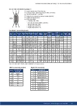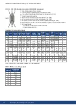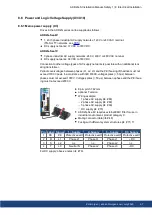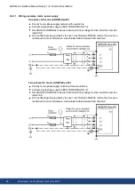
8.9 Motor Power, Brake and Feedback connection
The AKD2G drive is able to protect the connected motor from overloading, if the parameters
are set correctly and the thermal protection sensor is connected and supervised. With Koll-
morgen motors the valid data are automatically set by the WorkBench motor database. Refer
to parameter AXIS#.MOTOR.RTYPE for supported thermal sensors.
The dynamic voltage rise can lead to a reduction in the motor operating life and, on unsuit-
able motors, to flashovers in the motor winding.
Only install motors with insulation class F (acc. to IEC60085) or above.
Only install cables that meet the requirements (
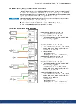
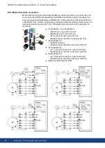
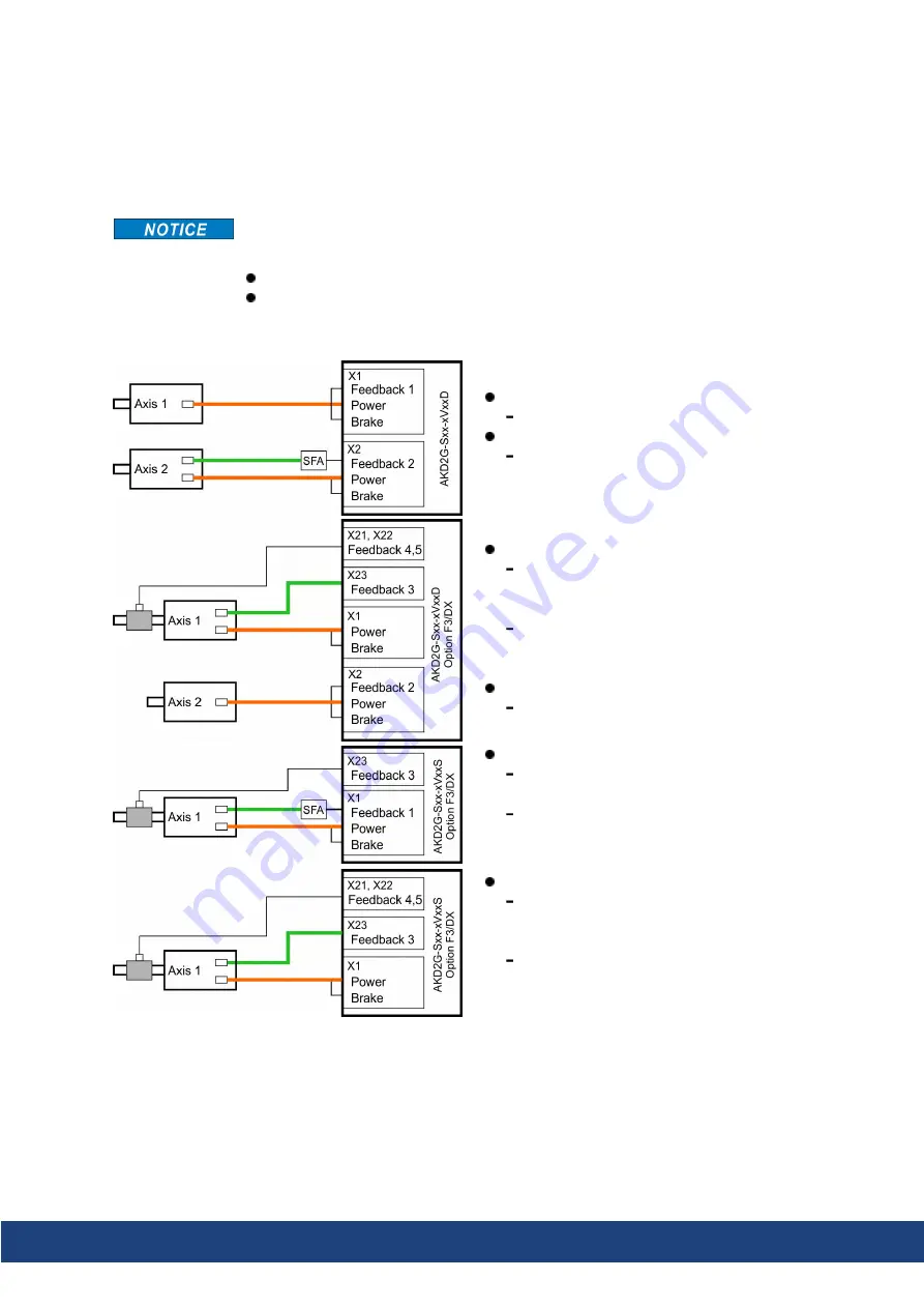
8.9.1 Motor connectivity, some examples
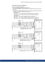
Axis 1: single cable connection (
commutation feedback: SFD3 or DSL
Axis 2: dual cable connection (
commutation feedback: EnDAT, HIPERFACE,
Resolver etc. by using SFA
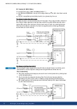
Axis 1: dual cable connection (
commutation feedback: Resolver, SFD, EnDAT,
HIPERFACE, BiSS, SinCos, ComCoder, Hall,
SmartAbs etc. by using X23
position feedback:
- X21: Step/Direction
- X22: Step/Direction or incremental encoder
Axis 2: single cable connection (
commutation feedback: SFD3 or DSL
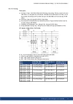
Axis 1: dual cable connection (
commutation feedback: EnDAT, HIPERFACE,
Resolver etc. by using SFA
position feedback:Resolver, SFD, EnDAT,
HIPERFACE, BiSS, SinCos, ComCoder, Hall,
SmartAbs etc. by using X23
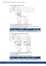
Axis 1: dual cable connection (
commutation feedback: Resolver, SFD, EnDAT,
HIPERFACE, BiSS, SinCos, ComCoder, Hall,
SmartAbs etc. by using X23
position feedback:
- X21: Step/Direction
- X22: Step/Direction or incremental encoder
AKD2G-S Installation Manual, Safety 1 | 8 Electrical Installation
Kollmorgen | kdn.kollmorgen.com | July 2020
79

