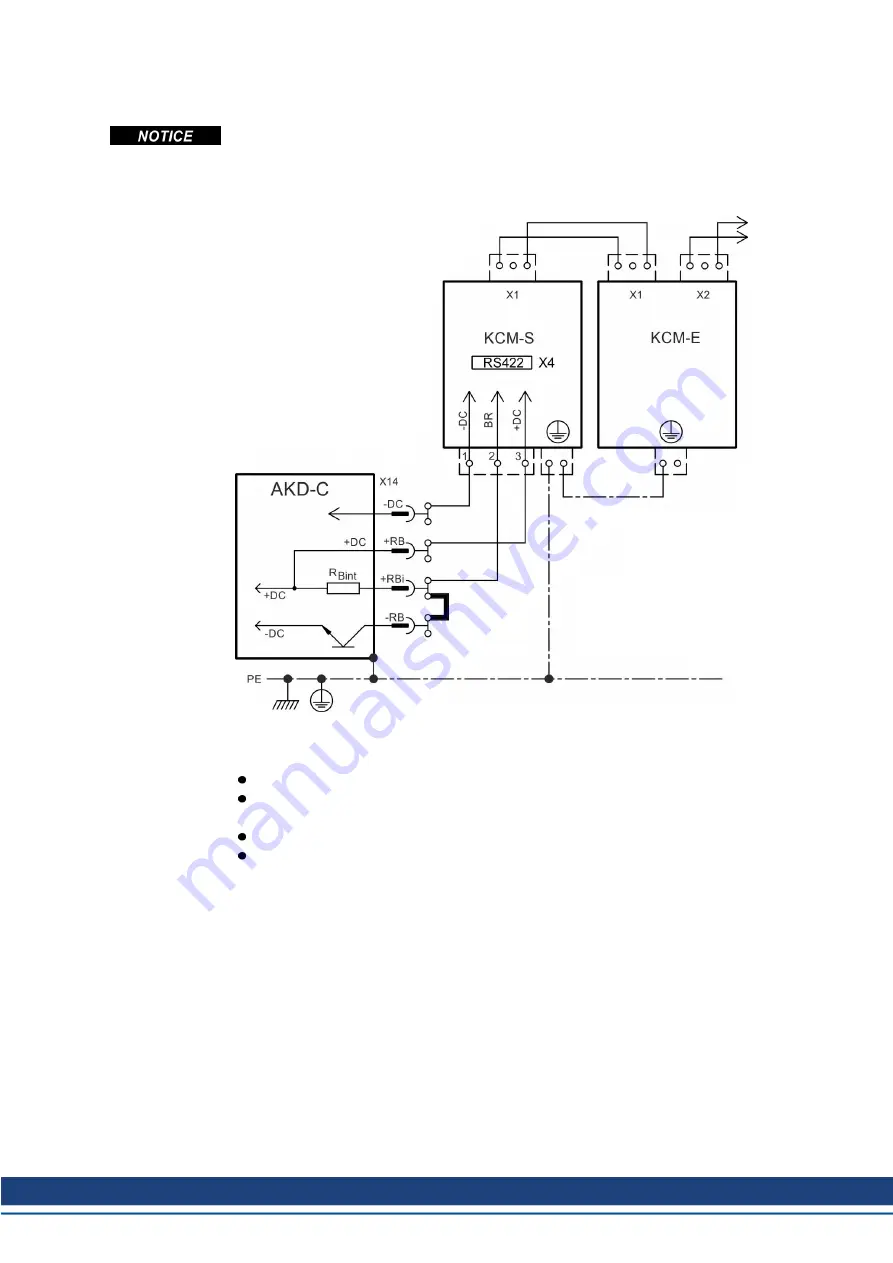
9.8.2.2 Example installation with KCM-S and KCM-E
Maximum cable length between AKD-C and KCM: 500mm. The DC+ and DC- lines should
always be twisted, maximum cross section is 6mm². Ensure that the polarity is correct,
swapping round DC+/DC- will damage the KCM modules.
Create a motion profile that causes the brake chopper to respond.
Setup KCM-S and KCM-E
Prerequisite for the following instructions:
Properly disconnected, grounded system.
KCM-S: assembled and wired in the switching cabinet. The load that leads to the activ-
ation of the brake chopper during braking must be connected.
KCM-E: assembled and connected to the KCM-S with connection cable (X1) and PE line.
Discharge aids (plug-in bridge) are removed.
Proceed as instructed below:
1. Switch on the line voltage after the AKD-C has finished the 24V boot process.
2. Enable the AKD and operate the motion profile that causes the brake chopper to respond.
3. The KCM-S determines the chopper threshold and begins to charge; LED (top view)
flashes. The energy stored in the capacitor module during generative braking is available
the next time acceleration happens.
RS422 interface X4 allows data exchange controlled by a terminal software of your choice.
Interface setting: 115200 Baud, 8 Data Bits, 1 Stop Bit, No Parity&Flow Control.
The X4 mating connector is in the package. More information is given in the KCM Instruc-
tions Manual.
AKD-C Installation | 9 Electrical Installation
Kollmorgen | kdn.kollmorgen.com | February 2018
67


