


-12-
Fig. 8
Fig. 9
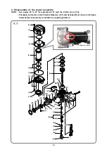
1. Disassembly
• Remove Housing (C)
[48]
and magazine ass'y referring to page 9 to 10.
• For safety, push the valve core once more and check that compressed air is completely released and the
Piston Ass'y
[16]
is lowered to the bottom dead point referring to "Feeding compressed air" on page 29.
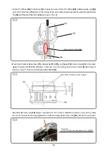
• Slide the Needle Cover
[43]
to the side of Pushing Lever (B)
[40]
and remove the Needle Roller D2.5
[41]
using a tapered tool.
NOTE: Pay attention not to drop the Needle Roller D2.5 [41] in the Housing Ass'y [50].
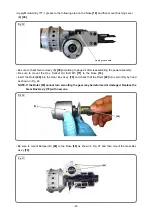
• Turn the Adjuster
[42]
and remove Pushing Lever (A)
[44]
, Probe
[45]
, and Needle Roller D3 x 10.4
[46]
.
• Remove the Needle Cover
[43]
from the Adjuster
[42]
.
2. Reassembly
Reverse the disassembly procedure to reassemble. Note the following points.
CAUTION: Adjustment of the Adjuster [42] is required when reassembling Pushing Lever (A) [44]. If
adjusted incorrectly, the nailer cannot drive nails or nails cannot be driven into the holes
of the metal connectors properly.
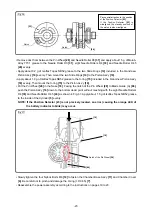
<Adjustment method of the Adjuster
[42]
>
• Mount the Needle Cover
[43]
to the Adjuster
[42]
. Slide the Needle Cover
[43]
to the side of Pushing Lever
(B)
[40]
without fitting in the groove.
• Make a gap about 4 mm between Pushing Lever (A)
[44]
and Adjuster
[42]
and align the groove of the
Adjuster
[42]
with the hole of Pushing lever (A)
[44]
(Fig. 10).
Disassembly and reassembly of the probe and pushing lever (A)
[44]
[42]
[43]
[41]
[44]
[46]
[45]
[43]
[42]
Fig. 10
[42]
[43]
4 mm
[44]
[16]
Align the groove of the Adjuster
[42]
with
the hole of Pushing Lever (A)
[44]
.