


-30-
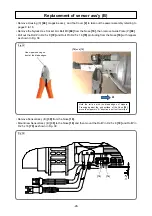
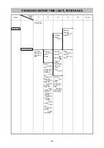
Fig. 42
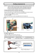
Fig. 43
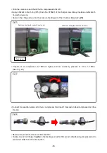
Fig. 44
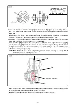
• Push the valve core and check that no compressed air is left.
• Apply lubricant to the O-ring (S-5) (Code No. 872822) of the charge screw. Always replace a defective O-
ring with a new one.
• Screw in the charge screw into the pressure feeding port of the Chamber Base Ass’y
[11]
.
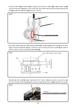
• Prepare an air compressor (0.7 MPa or higher) and set a delivery pressure of 0.7 to 1.2 MPa.
(See Fig. 43.)
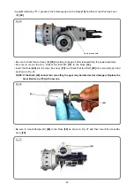
• Connect the reduction valve set to the air compressor for at least 10 seconds to feed compressed air. (See
Fig. 44.)
• Reverse the procedure above for disconnection.
• Quickly mount the Charge Cap
[8]
on the feeding port within 30 seconds after feeding compressed air to
prevent air leaks from the valve section.
Before connecting the reduction valve set
After connecting the reduction valve set
Feeding port


