


-14-
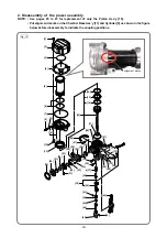
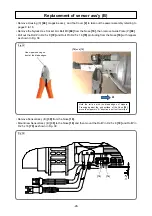
Fig. 12
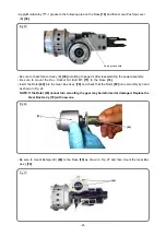
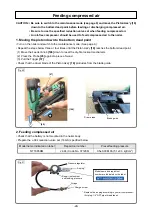
Fig. 11-3
• Put the Needle Roller D2.5
[41]
into the hole of the Adjuster
[42]
and slide the Needle Cover
[43]
to the
groove of the Adjuster
[42]
.
NOTE: Pay attention not to drop the Needle Roller D2.5 [41] in the Housing Ass'y [50].
• Check that the Probe
[45]
and Pushing Lever (A)
[44]
move smoothly without any catch.
• Check that the Adjuster
[42]
does not turn.
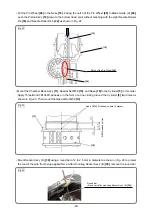
OK: • Piston Ass’y
[16]
does not contact
the J-409 push lever gauge.
• Nailer is vertical.
[16]
[86]
J-409 push lever gauge
[45]
NG: • Piston Ass’y
[16]
contacts the
J-409 push lever gauge.
• Nailer is tilted.
J-409 push lever gauge
(Code No. 377657)
J-409 push lever gauge
1
2
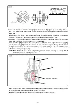
Power switch
Operation panel
(
4
)
(
5
)
[42]
[44]
3
The tool is powered on while this LED is lighting.
5.2 mm groove
(4.5 mm groove)
4.5 mm groove
5.2 mm groove