


TS_600_00 PW1000 1-3kVA User Manual 6/4/17
39
7: Options
Once installed, the UPS-Management software agent, which is already installed in the card, monitors the UPS operation
and outputs its data in SNMP format to the connected network. The card enables automated generation of event/alarm
emails, server controlled shut down (with optional licenses) and other tasks, and can also be integrated with BMS software
over a local area network (LAN) for SNMP or Modbus information over IP.
Uninterruptible Power Supplies Ltd. offer monitoring software with SNMP functionality for Novell, OS/2, and Windows that
run both on INTEL and on ALPHA, DEC VMS and Apple.
An optional external SNMP adapter can be connected to the UPS via its RS232 port if the UPS card slot is in use (e.g.
DCE card fitted) but SNMP facilities are still required.
RCCMD
RCCMD (Remote Console Command Module) for ‘multi-server shut down’ is an independent software module intended
for transmitting and receiving ‘remote commands’. Using the ‘RCCMD send’ function, the SNMP adapter can send status
messages to connected users or initiate automatic shut down throughout the whole network. Our CS141 SNMP adapters
are fully compatible with RCCMD.
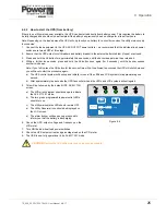
7.5
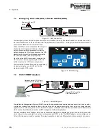
AS400 (dry contact) card
The DCE dry contact card provides volt-free
signalling outputs that can be integrated into an
external alarm monitoring panel or building
management system.
All the output connections at pins 1-7 are
switched by relays whose pole contacts are
connected to terminal 8 (common). Figure 7.5
shows an example of the
INVERTER
ON
relay.
Note that all the outputs to terminals 1-7 are link-
selectable to be either short-circuited or open-
circuited to the common Pin 8 when the
monitored parameter is ‘active’. Details for
configuring the links are provided in the
documentation that accompanies the card.
Terminals 9 an 10 are inputs that can be used to
shut down the UPS when en external voltage of
6-25VDC is applied, as shown.
AC
IN
P
U
T
AC OUTPUT
INPUT BREAKER
EXT> BAT.
INTERFACE
1
2
EP
O
RS
2
3
2
USB
1
2
3
4
5
6
7
8
9
10
UPS ON-BYPASS
DCE CARD
UTILITY ABNORMAL (n/c contact)
UTILITY NORMAL (n/o contact)
INVERTER ON
BATTERY LOW
BATTERY ABNORMAL
UPS ALARM
COMMON
6-25VDC
Relay contacts
SHUT DOWN UPS (+ve signal)
SHUT DOWN UPS (-ve signal)
Figure 7.5 Dry Contact card (DCE)


