


TS_600_00 PW1000 1-3kVA User Manual 6/4/17
17
3: Installation
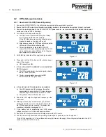
3.3
Assembling the UPS mounting hardware
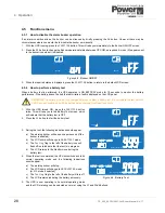
3.3.1 Hardware accessories pack
The accessories pack which is shipped inside the UPS packing carton contains all the hardware required to safely install
your UPS as a tower or rack-mounted system.
Figure 3.3 Accessories pack
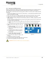
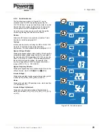
3.3.2 Stand-alone Tower assembly
1. Turn the UPS on its side and,
using screws (D) provided,
attach the four tower feet (A) to
the base of the enclosure as
shown in Figure 3.4.
Note: You will have to remove
the M3 screws already fitted to
the UPS side panels in order to
make way for the new feet
attachments.
2. Carefully lift the assembly and
stand it on its feet.
3. If necessary, rotate the UPS
LCD control panel so that it is
correctly orientated. To achieve
this, carefully pull the control
panel forward to unclip it from its
mounting, rotate it to the correct angle, then relocate it and press it back into place.
4. This completes the tower hardware configuration.
3.3.3 Rack installation
The PW1000 1-3kVA UPS and battery enclosure(s) can be installed on adjustable mounting rails fitted in a standard 19
inch rack.
If the UPS is to be connected to an external batteries, you should install the battery cabinet(s) immediately
below the UPS following the same procedure as for mounting the UPS. The UPS/Battery enclosures are then connected
together using the supplied cable.
Due to their relative weights, it is preferable to mount UPS and battery enclosures near the bottom of the rack.
Key Point:
Always mount the batteries below the UPS and as far away from other heat-generating sources as
possible.
A
B
C
D
E
F
G
A
x4 Tower feet
E
x8 M3 x 6mm Countersunk
B
x2 Rack mounting handles
F
x6 M4 x 8mm Countersunk
C
x2 Rack mounting side-plates
G
x1 EPO connecting socket
D
x8 M3 x 6mm Domed
A
D
Figure 3.4 Tower assembly


