TP-6073 4/06
62
Section 10 Wiring Diagrams
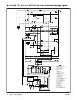
10.1 Remote Start Panel
Start
P
P
K1
70
47
43
N
Gen. ON light
Remote
switch
P3-5
P3-6
P3-1
P2-3
P2-7
P2-8
P2-9
K2
P1-14
47
P2-4
43
P2-5
P2-6
N
P1-9
N
+
--
Relay
circuit
board
Local
switch
Violet
Black
Yellow/
Red
Grey/
Black
Start
Stop
Stop
10-amp
fuse
P3-4
J3-4
J3-5
J3-1
J3-6
TP-5588-7
10.2 Remote Start and Two-Meter
Panel
P3-2
J3-2
Start
P
P
7C
K1
70
47
43
N
Oil pressure
gauge
Water temp.
gauge
Gen. ON light
Remote
switch
5
P3-5
P3-6
P3-1
P3-3
P2-3
P2-7
P2-8
P2-9
P4-2
P4-3
K2
P1-14
47
P2-4
43
P2-5
P2-6
N
P1-9
N
+
--
Relay
circuit
board
Local
switch
Violet
Tan
Black
Yellow/
Red
Grey/
Black
L. Blue
Start
Stop
Stop
10-amp
fuse
P3-4
W.T.
sender
O.P.
sender
J3-4
J3-5
J3-6
J3-1
J3-3
TP-5588-7
Summary of Contents for 10EOR
Page 10: ...10 Safety Precautions and Instructions TP 6073 4 06 Notes...
Page 12: ...TP 6073 4 06 12 Service Assistance Notes...
Page 22: ...TP 6073 4 06 22 Section 3 Intake and Exhaust System Notes...
Page 26: ...TP 6073 4 06 26 Section 4 Fuel System Notes...
Page 30: ...TP 6073 4 06 30 Section 5 Cooling System Notes...
Page 38: ...TP 6073 4 06 38 Section 6 Controller Troubleshooting Notes...
Page 54: ...TP 6073 4 06 54 Section 8 Component Troubleshooting Notes...
Page 60: ...TP 6073 4 06 60 Section 9 Generator Disassembly Reassembly Notes...
Page 82: ...TP 6073 4 06 82...
Page 83: ...TP 6073 4 06 83...


